


-
Lasers with cavities consisting of retroreflecting elements can give the potential for large-dynamic-range alignment-free operation, which makes the important applications in adaptive wireless laser power transfer/communication possible. In such an emerging approach based on resonant laser beam in the cavity, the laser is delivered to the photovoltaic cell for charging application (or photodiode for communication application) at the receiver automatically, without the necessity of positioning and aiming the receiver in conventional laser wireless power transfer techniques. The laser capable of operating alignment-free efficiently across large-dynamic-range is essential for the application. In this work, the requirements for the dynamic range of alignment-free operation are summarized. An alignment-free laser with a cavity consisting of cat-eye retroreflectors is designed, and a large alignment-free dynamic range as never before is experimentally demonstrated. Telescope system in the laser cavity is adopted to suppress the beam expansion to enhance the working distance between the laser transmitter and the receiver. Coupled cavity scheme is used to reduce the laser intensity between the transmitter and the receiver for laser safety. By calculating the stability zone of the laser cavity, it is found that the stability zone of the receiver cat-eye distance is quite narrow. Hence, the laser operation is very sensitive to the defocusing of the cat eye defocusing. Moreover, the cat eye defocusing induced by optical aberrations of spherical aberration and field curvature can be rather serious, when the long working distance results in a large beam size and the angle of incidence is large, hence limiting the effective working distance and the field of view of the alignment-free laser significantly. In the experiment, the improved optical designs with the aberrations compensation are adopted for large-dynamic-range alignment-free operation. The end-pumped Nd:GdVO4 laser at 1063 nm can deliver over 5-W output within a working distance range of 1–5 m, and a receiver field of view of ±30°, without cavity realignment. The transmitter field of view reaching 4.6° (full width at half maximum) at a working distance of 5 m is also realized, with a corresponding receiver transverse movement range of 40 cm. Our work clarifies the optimizing criteria of the large-dynamic-range alignment-free laser based on cat-eye retroreflectors.
-
Keywords:
- alignment-free laser /
- cat-eye retroreflector /
- cavity stability zone /
- optical aberration
[1] Jin K, Zhou W Y 2019 IEEE Trans. Power Electron. 34 3842
 Google Scholar
[2] Liu Q W, Wu J, Xia P F, Zhao S J, Yang Y P, Chen W, Hanzo L 2016 IEEE Veh. Technol. Mag. 11 36
Google Scholar
[3] Alpert O, Paschotta R 2016 US Patent 9312660 B2
[4] Alpert O, Ronen E, Nahmias O, Mor O R, Golan L, Sagi R 2019 US Patent 10193297 B2
[5] Liu Q W, Xiong M L, Liu M Q, Jiang Q W, Fang W, Bai Y F 2022 IEEE Internet Things J. 9 13876
Google Scholar
[6] Lim J Y, Khwaja T S, Ha J Y 2019 Opt. Express 27 A924
Google Scholar
[7] Wang W, Gao Y X, Sun D, Du X, Guo J, Liang X Y 2021 Chin. Opt. Lett. 19 111403
Google Scholar
[8] Zhang Z, Zhang J W, Zhou Y L, Zhang X, Li Z W, Zhang J Y, Zhang J, Gong Y X, Liu T J, Mu J F, Ning Y Q, Qin L, Wang L J 2022 Opt. Express 30 22364
Google Scholar
[9] Javed N, Nguyen N L, Naqvi S F A, Ha J Y 2022 Opt. Express 30 33767
Google Scholar
[10] Huang J J, Li X, Zhang J P 2021 9th International Conference on Intelligent Computing and Wireless Optical Communications, Chongqing, China, June 4–7, 2021 p1
[11] Sheng Q, Wang M, Ma H C, Qi Y, Liu J J, Xu D G, Shi W, Yao J Q 2021 Opt. Express 29 34269
Google Scholar
[12] Sheng Q, Wang A H, Wang M, Ma H C, Qi Y, Liu J J, Wang S J, Xu D G, Shi W, Yao J Q 2022 Opt. Laser Technol. 151 108011
Google Scholar
[13] Innocenzi M E, Yura H T, Fincher C L, Fields R A 1990 Appl. Phys. Lett. 56 1831
Google Scholar
[14] Sheng Q, Wang A H, Ma Y Y, Wang S J, Wang M, Shi Z, Liu J J, Fu S J, Shi W, Yao J Q, Omatsu T 2022 Photoni X 3 4
Google Scholar
[15] 刘俊杰, 盛泉, 王盟, 张钧翔, 耿兴宁, 石争, 王爱华, 史伟, 姚建铨 2022 物理学报 71 014204
Google Scholar
Liu J J, Sheng Q, Wang M, Zhang J X, Geng X N, Shi Z, Wang A H, Shi W, Yao J Q 2022 Acta Phys. Sin. 71 014204
Google Scholar
[16] Wang M, Ma Y Y, Sheng Q, He X, Liu J J, Shi W, Yao J Q, Omatsu T 2021 Opt. Express 29 27783
Google Scholar
[17] Sheng Q, Wang A H, Qi Y, Wang M, Shi Z, Geng J N, Liu J J, Wang S J, Fu S J, Shi W, Yao, J Q 2022 Results Phys. 37 105558
Google Scholar
[18] 刘俊杰, 齐岳, 盛泉, 王思佳, 王盟, 徐德刚, 史伟, 姚建铨 2022 红外与激光工程 51 20211108
Google Scholar
Liu J J, Qi Y, Sheng Q, Wang S J, Wang M, Xu D G, Shi W, Yao J Q 2022 Infrared Laser Eng. 51 20211108
Google Scholar
[19] Liu J J, Wang A H, Sheng Q, Qi Y, Wang S J, Wang M, Xu D G, Fu S J, Shi W, Yao J Q 2022 Chin. Opt. Lett. 20 031407
Google Scholar
[20] Lumb M P, Meitl M, Wilson J, Bonafede S, Burroughs S, Forbes D V, Bailey C G, Hoven N M, Hoheisel R, Yakes M K, Polly S J, Hubbard S M, Walters R J 2014 IEEE 40th Photovoltaic Specialist Conference, Denve, USA, June 8–13, 2014 p0491
-

图 1 基于跟瞄的激光无线传能(a)和谐振激光自适应无线传能(b)示意图
Figure 1. Schematic of the (a) conventional laser power transfer based on acquisition, tracking, and pointing (ATP) system and (b) adaptive resonant beam wireless laser power transfer/communication.

图 2 免调试激光器的工作距离、接收端视场和发射端视场
Figure 2. Working distance, receiver FoV and transmitter FoV of the alignment-free laser.
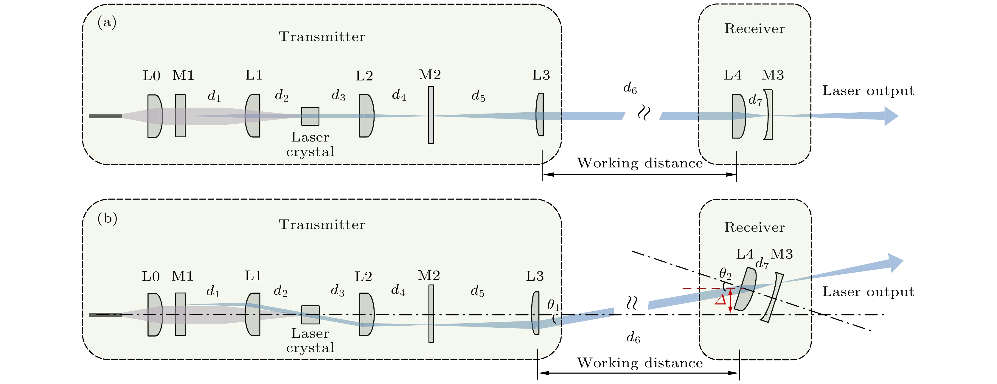
图 3 免调试激光器光路示意图 (a)接收端位于发射端光轴上且朝向发射端; (b)接收端相对发射端光轴存在偏离, 且朝向与振荡光路存在夹角
Figure 3. Schematic of the alignment-free laser: (a) The receiver and the transmitter are on the optical axes of each other; (b) the receiving end deviates from the optical axis of the transmitting end, and the orientation has an angle with the oscillating optical path.

图 4 不同工作距离d6下接收端猫眼间距d7的稳区
Figure 4. Stability zones of receiver CER distance d7 as a function of working distance d6.

图 5 使用f = 25 mm的K9平凸球面透镜时球差导致的猫眼逆反射器离焦
Figure 5. CER defocusing induced by the spherical aberration of a K9 plano-convex spherical lens with f = 25 mm.
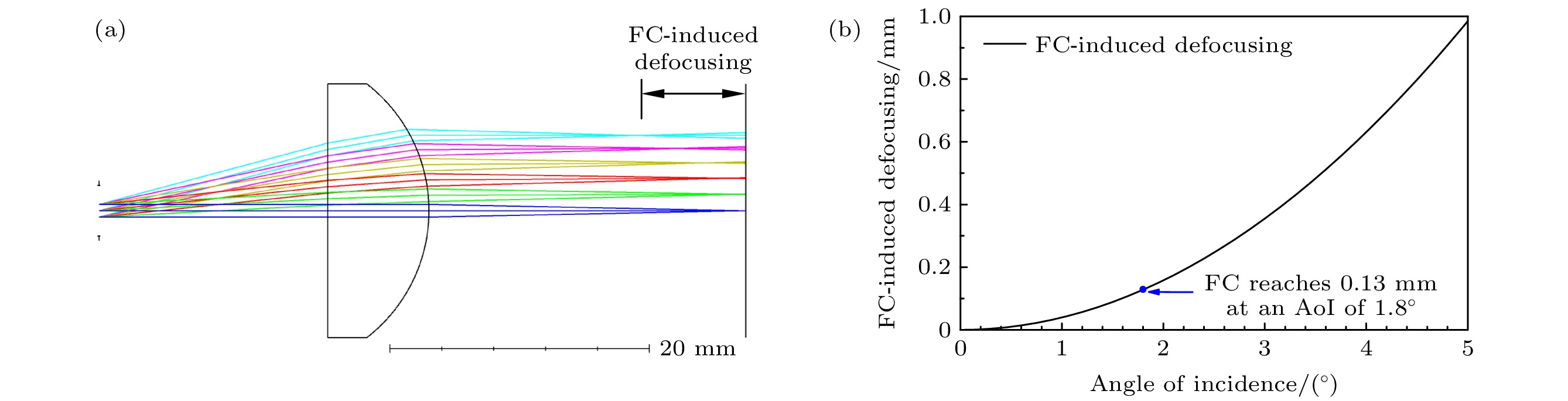
图 6 使用f = 25 mm的K9平凸透镜时场曲导致的猫眼逆反射器离焦
Figure 6. CER defocusing induced by the field curvature of a K9 plano-convex lens with f = 25 mm.

图 7 不同接收端透镜球差条件下激光器的工作距离特性实验结果
Figure 7. The experimental working distance behavior of the laser using receiver lenses with different SA.

图 8 不同接收端透镜场曲条件下的接收端视场特性实验结果
Figure 8. The experimental receiver FoVs with and without FC of the receiver CER compensated.
表 1 计算和实验中所用参数
Table 1. Parameters used in the experiment and calculation.
Lenses Focal length/mm Distances Length/mm L0 10 d1 23.8 L1 24.6 d2 23 L2 24.6 d3 23.8 L3 48.3 d4 23 L4 25, 50 (51.8) d5 49.1 ft 500 d6 1000—5000  DownLoad: CSV
表 2 面向谐振激光自适应无线传能/通信应用的免调试激光器典型实验结果
Table 2. Typical experimental results of alignment-free lasers for adaptive resonant beam charging/communication applications
Year Retro-
reflectorLaser gain
mediumOutput power/W Optical efficiency/% Working distance/m Receiver FoV/(°) Transmitter FoV/(°) 2019[6] Corner cube SOA 0.0017 — 1 — 6.6°
(only one dimension)2021[7] CER Nd:YVO4 disk >10 — 0.15 ±13°
@ 0.15 m±8.3°@0.15 m
(0 output)2022[8] Ball lens EDFA 0.4 — 30 Unlimited — 2022[5] CER Nd:YVO4 disk >10 ~15 <3 — ±5.1°@2 m
(0 output)2022[9] CER Optically pumped VECSEL 0.863 0.57 2 — 1.37°@0.5 m
0.47°@2 m2021[10] CER — 0.012 — 2 — — Our work CER Bulk Nd:GdVO4 >5 >30 >5 ±30°@5 m 4.6°@5 m
(half maximum)
DownLoad: CSV
-
[1] Jin K, Zhou W Y 2019 IEEE Trans. Power Electron. 34 3842
Google Scholar
[2] Liu Q W, Wu J, Xia P F, Zhao S J, Yang Y P, Chen W, Hanzo L 2016 IEEE Veh. Technol. Mag. 11 36
Google Scholar
[3] Alpert O, Paschotta R 2016 US Patent 9312660 B2
[4] Alpert O, Ronen E, Nahmias O, Mor O R, Golan L, Sagi R 2019 US Patent 10193297 B2
[5] Liu Q W, Xiong M L, Liu M Q, Jiang Q W, Fang W, Bai Y F 2022 IEEE Internet Things J. 9 13876
Google Scholar
[6] Lim J Y, Khwaja T S, Ha J Y 2019 Opt. Express 27 A924
Google Scholar
[7] Wang W, Gao Y X, Sun D, Du X, Guo J, Liang X Y 2021 Chin. Opt. Lett. 19 111403
Google Scholar
[8] Zhang Z, Zhang J W, Zhou Y L, Zhang X, Li Z W, Zhang J Y, Zhang J, Gong Y X, Liu T J, Mu J F, Ning Y Q, Qin L, Wang L J 2022 Opt. Express 30 22364
Google Scholar
[9] Javed N, Nguyen N L, Naqvi S F A, Ha J Y 2022 Opt. Express 30 33767
Google Scholar
[10] Huang J J, Li X, Zhang J P 2021 9th International Conference on Intelligent Computing and Wireless Optical Communications, Chongqing, China, June 4–7, 2021 p1
[11] Sheng Q, Wang M, Ma H C, Qi Y, Liu J J, Xu D G, Shi W, Yao J Q 2021 Opt. Express 29 34269
Google Scholar
[12] Sheng Q, Wang A H, Wang M, Ma H C, Qi Y, Liu J J, Wang S J, Xu D G, Shi W, Yao J Q 2022 Opt. Laser Technol. 151 108011
Google Scholar
[13] Innocenzi M E, Yura H T, Fincher C L, Fields R A 1990 Appl. Phys. Lett. 56 1831
Google Scholar
[14] Sheng Q, Wang A H, Ma Y Y, Wang S J, Wang M, Shi Z, Liu J J, Fu S J, Shi W, Yao J Q, Omatsu T 2022 Photoni X 3 4
Google Scholar
[15] 刘俊杰, 盛泉, 王盟, 张钧翔, 耿兴宁, 石争, 王爱华, 史伟, 姚建铨 2022 物理学报 71 014204
Google Scholar
Liu J J, Sheng Q, Wang M, Zhang J X, Geng X N, Shi Z, Wang A H, Shi W, Yao J Q 2022 Acta Phys. Sin. 71 014204
Google Scholar
[16] Wang M, Ma Y Y, Sheng Q, He X, Liu J J, Shi W, Yao J Q, Omatsu T 2021 Opt. Express 29 27783
Google Scholar
[17] Sheng Q, Wang A H, Qi Y, Wang M, Shi Z, Geng J N, Liu J J, Wang S J, Fu S J, Shi W, Yao, J Q 2022 Results Phys. 37 105558
Google Scholar
[18] 刘俊杰, 齐岳, 盛泉, 王思佳, 王盟, 徐德刚, 史伟, 姚建铨 2022 红外与激光工程 51 20211108
Google Scholar
Liu J J, Qi Y, Sheng Q, Wang S J, Wang M, Xu D G, Shi W, Yao J Q 2022 Infrared Laser Eng. 51 20211108
Google Scholar
[19] Liu J J, Wang A H, Sheng Q, Qi Y, Wang S J, Wang M, Xu D G, Fu S J, Shi W, Yao J Q 2022 Chin. Opt. Lett. 20 031407
Google Scholar
[20] Lumb M P, Meitl M, Wilson J, Bonafede S, Burroughs S, Forbes D V, Bailey C G, Hoven N M, Hoheisel R, Yakes M K, Polly S J, Hubbard S M, Walters R J 2014 IEEE 40th Photovoltaic Specialist Conference, Denve, USA, June 8–13, 2014 p0491

 DownLoad:
Catalog
Metrics
- Abstract views: 6668
- PDF Downloads: 112
- Cited By: 0
