


-
微纳米马达是建立微流体环境与宏观操控的桥梁, 气泡微马达的驱动速度高, 这一优势在实际应用中不可替代. 管式气泡马达适用于复杂场景但能量转化率低, 气泡驱动的Janus微球马达效率高但仅适用于气液界面附近. 鉴于此, 本文提出通过双气泡聚并方式驱动Janus微球马达的新体系, 调和了高能量转化率与界面受限的矛盾. 在实验中, 借助高速摄像记录了双气泡聚并驱动微马达的~100 μs级过程, 气泡聚并紧邻微球发生, 通过释放的能量驱动微球显著运动, 其融合过程是独特的可动曲壁受限下的气液界面演化问题. 进一步结合伪势格子Boltzmann数值方法探究了气泡聚并驱动的流体动力学机制. 研究结果揭示了不同时段气泡聚并的细节, 给出了气泡颗粒尺寸比等因素对微球位移、初始动能转换率的影响, 确认了双气泡聚并释放表面能的高效驱动机制.
-
关键词:
- 双气泡聚并 /
- 微马达 /
- 界面能 /
- 伪势格子Boltzmann方法
Self-propelled micromotor serves as a bridge between the microfluidic environment and macroscopic control. It has broad application prospects in targeted drug delivery, biosensors, and other fields. The high driving speed of bubble micromotor is an irreplaceable advantage in practical applications. Bubble micromotor converts chemical energy in ambient solutions into mechanical energy through asymmetric surface catalytic reactions to drive its own motion. The energy conversion rate of bubble driving is used as an indicator to evaluate the driving force. The Pt catalytic layer of a tubular micromotor is located on the inner wall of the microtube. Bubbles form inside the tube. They are released from one end of the microtubule into the solution and self driven by bubble rebound, with an energy conversion rate of $ \sim {10^{ - 10}}$ . The Janus microsphere motor near the gas-liquid interface utilizes the energy of the bubble coalesced with the interface to drive the microsphere, with an energy conversion rate of$ \sim {10^{ - 7}}$ . In sum, the tubular bubble motor is suitable for complex scenarios but has a low energy conversion rate. The Janus microsphere motor driven by bubbles has a high efficiency but is only suitable near the gas-liquid interface. This paper combines the advantages of driving tubular micromotors in bulk solution and Janus microsphere motors which can be driven efficiently by interface energy, proposes a new method of driving Janus microsphere motors by dual bubble coalescence.In the experiment, a high-speed camera is used to record the ~100 μs of dual bubble coalescence and the process of driving micromotor. Then we investigate the initial kinetic energy conversion rate of micro motor driven by bubble coalescence. Three sets of different bubble/particle size ratios of ${R_{\rm{b}}}/{R_{\rm{p}}} < 1$ ,${R_{\rm{b}}}/{R_{\rm{p}}} \approx 1$ ,${R_{\rm{b}}}/{R_{\rm{p}}} > 1$ are adopted for their propulsion effects on microspheres. The initial kinetic energy conversion rate is defined to characterize the contribution of bubble coalescence process to microsphere driving.After simulations with the pseudo potential lattice Boltzmann method, the mechanism of bubble coalescence driving the motion of microspheres is revealed. It is clarified that the interface oscillation caused by bubble coalescence is the main reason of driving the micromotor, and its energy conversion rate is between the rebound driving of the tubular micromotor and the one-bubble coalescence driving with the free surface. The research results reveal the details of bubble coalescence at different time periods, and provide the effects of factors such as bubble particle size ratio on microsphere displacement and initial kinetic energy conversion rate. Thus the efficient driving mechanism of dual bubble coalescence and release of surface energy are confirmed. -
Keywords:
- dual bubble coalescence /
- micromotor /
- interface energy /
- pseudo potential lattice Boltzmann method
[1] Wang L L, Chen L, Zheng X, Yu Z X, Lü W C, Sheng M J, Wang L N, Nie P C, Li H Y, Guan D S, Cui H H 2022 Small 18 2203872
 Google Scholar
[2] 李茂垚, 吴建荣, 郑元义 2020 科学通报 65 4123
Google Scholar
Li M Y, Wu J R, Zheng Y Y 2020 Chin. Sci. Bull. 65 4123
Google Scholar
[3] Li M, Xi N, Wang Y C, Liu L Q 2021 IEEE Trans. Biomed. Eng. 68 130
Google Scholar
[4] Liu L, Wang D W, Rao W 2021 Micromachines 12 280
Google Scholar
[5] Wang W, Duan W T, Ahmed S, Mallouk T E, Sen A 2013 Nano Today 8 531
Google Scholar
[6] Feng Y W, Jia D L, Yue H E, Wang J, Song W P, Li L Q, Zhang A M, Li S, Chang X C, Zhou D K 2023 Small 19 2207565
Google Scholar
[7] Baraban L, Streubel R, Makarov D, Han L Y, Karnaushenko D, Schmidt O G, Cuniberti G 2013 ACS Nano 7 1360
Google Scholar
[8] Pavlick R A, Sengupta S, McFadden T, Zhang H, Sen A 2011 Angew. Chem. Int. Ed. 50 9374
Google Scholar
[9] 郑旭, 崔海航, 李战华 2017 科学通报 62 167
Google Scholar
Zheng X, Cui H H, Li Z H 2017 Chin. Sci. Bull. 62 167
Google Scholar
[10] Wang S J, Wu N 2014 Langmuir 30 3477
Google Scholar
[11] Manjare M, Yang B, Zhao Y P 2012 Phys. Rev. Lett. 109 128305
Google Scholar
[12] 魏梦举, 陈力, 伍涛, 张鸿雁, 崔海航 2017 物理学报 66 164702
Google Scholar
Wei M J, Chen L, Wu T, Zhang H Y, Cui H H 2017 Acta. Phys. Sin. 66 164702
Google Scholar
[13] Wang L L, Chen L, Zhang J, Duan J M, Wang L, Li Z H, Zheng X, Cui H H 2018 Langmuir 34 10426
Google Scholar
[14] Van Leeuwen J L 2010 Science 329 395
Google Scholar
[15] Noblin X, Rojas N O, Westbrook J, Llorens C, Dumais J 2012 Science. 335 1322
Google Scholar
[16] Naeem S, Naeem F, Manjare M, Liao F, Bolaños Quiñones V A, Huang G S, Li Y, Zhang J, Solovev A A, Mei Y F 2019 Appl. Phys. Lett. 114 033701
Google Scholar
[17] 张培赟, 黄高山, 门传玲, 梅永丰 2017 中国科学: 化学 47 14
Google Scholar
Zhang P Y, Huang G S, Men C L, Mei Y F 2017 Sci. Sin. Chem. 47 14
Google Scholar
[18] 孔磊, 牟方志, 姜玉周, 李小丰, 官建国 2017 科学通报 62 107
Google Scholar
Kong L, Mou F Z, Jiang Y Z, Li X F, Guan J G 2017 Chin. Sci. Bull. 62 107
Google Scholar
[19] Wrede P, Medina-Sanchez M, Fomin V M, Schmidt O G 2021 Small 17 2006449
Google Scholar
[20] Wang W, Chiang T Y, Velegol D, Mallouk T E 2013 J. Am. Chem. Soc. 135 10557
Google Scholar
[21] Kupershtokh A L, Medvedev D A, Karpov D I 2009 Comput. Math. Appl 58 965
Google Scholar
[22] Shan X W, Chen H D 1993 Phys. Rev. E 47 1815
Google Scholar
[23] 郭照立, 郑楚光 2009 格子Boltzmann方法的原理及应用 (北京: 科学出版社) 第160—165页
Guo Z L, Zheng C G 2009 Theory and Applications of Lattice Boltzmann Method (Beijing: Science Press) pp160–165 (in Chinese)
[24] Chen L, Yu Y, Lu J H, Hou G X 2014 Int. J. Numer. Methods Fluids 74 439
Google Scholar
[25] Martys N S, Chen H D 1996 Phys. Rev. E 53 743
Google Scholar
[26] Elgeti J, Winkler R G, Gompper G 2015 Rep. Prog. Phys. 78 056601
Google Scholar
-
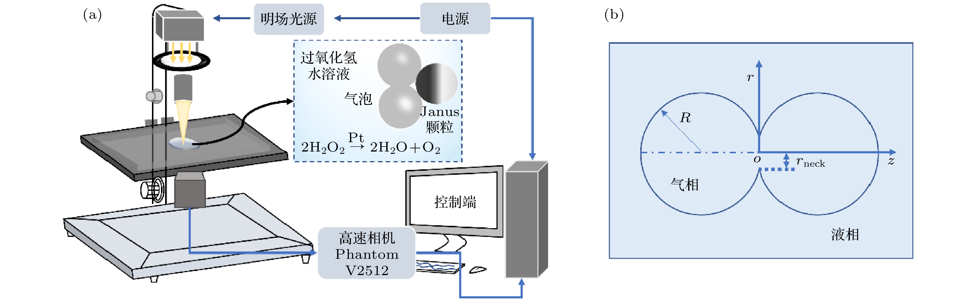
图 1 (a)实验装置示意图; (b)气泡聚并形状演化的方向定位
Fig. 1. (a) Schematic diagram of the experimental setup; (b) orientation of the evolution of bubble aggregation and shape.
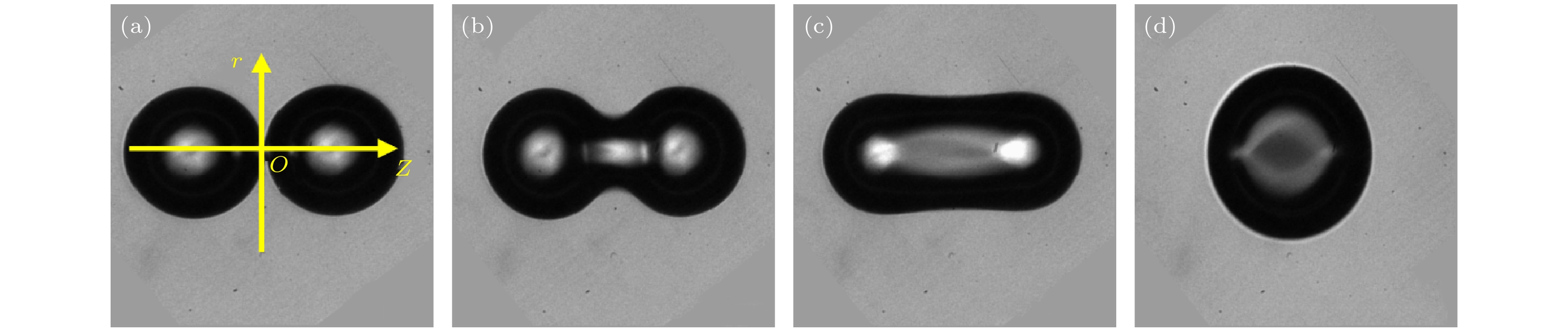
图 2 气泡聚集与界面演化的时间序列 (a) 0; (b) 4.34 μs; (c) 10.5 μs; (d) 43.39 μs
Fig. 2. Time series of bubble aggregation and interface evolution: (a) 0; (b) 4.34 μs; (c) 10.5 μs; (d) 43.39 μs.
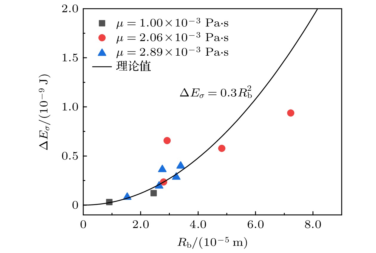
图 3 气泡聚并后表面能释放量随气泡半径变化图
Fig. 3. Variation of surface energy release with bubble radius after bubble aggregation.
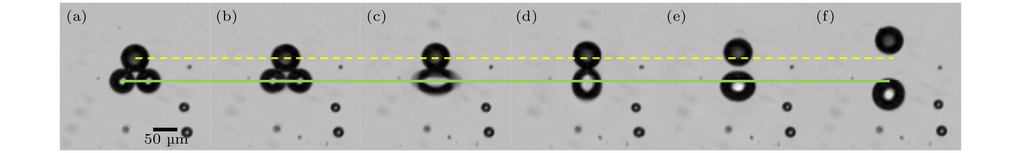
图 4 Rb1 = 24 μm, Rb2 = 25 μm, Rp = 27 μm时, 实验拍摄的气泡聚并驱动颗粒运动的时间序列(黄色虚线标示初始时刻颗粒的位置, 绿色虚线标示初始时刻聚并气泡中心) (a) 0; (b) 13.3 μs; (c) 26.6 μs; (d) 39.9 μs; (e) 66.6 μs; (f) 533.0 μs
Fig. 4. Experimentally filmed time series of bubbles aggregating and driving particle motion at Rb1 = 24 μm, Rb2 = 25 μm, Rp = 27 μm (Yellow dashed line marks the position of the particle at the initial moment, and the green dashed line marks the center of the aggregation bubble at the initial moment): (a) 0; (b) 13.3 μs; (c) 26.6 μs; (d) 39.9 μs; (e) 66.6 μs; (f) 533.0 μs.
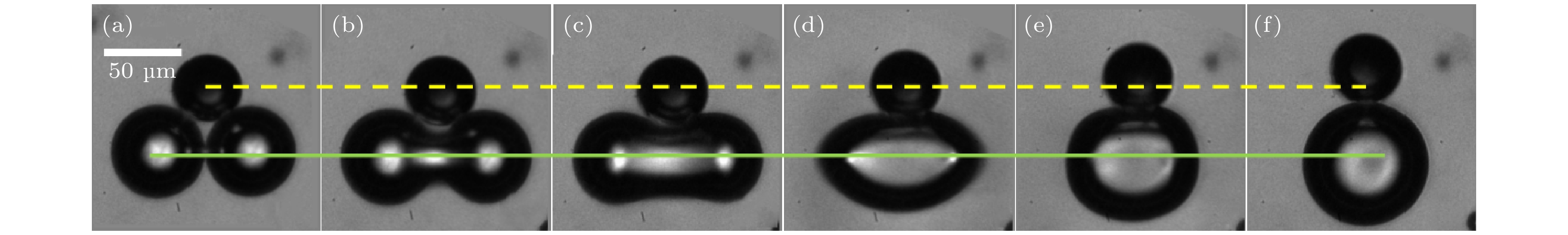
图 5 Rb1 = 47 μm, Rb2 = 49 μm, Rp = 36 μm时, 实验记录气泡聚并驱动颗粒运动序列图 (a) 0; (b) 5 μs; (c) 10 μs; (d) 20 μs; (e) 30 μs; (f) 200 μs
Fig. 5. Experimentally recorded bubble aggregation and driven particle motion sequence diagram at Rb1 = 47 μm, Rb2 = 49 μm, Rp = 36 μm: (a) 0; (b) 5 μs; (c) 10 μs; (d) 20 μs; (e) 30 μs; (f) 200 μs.
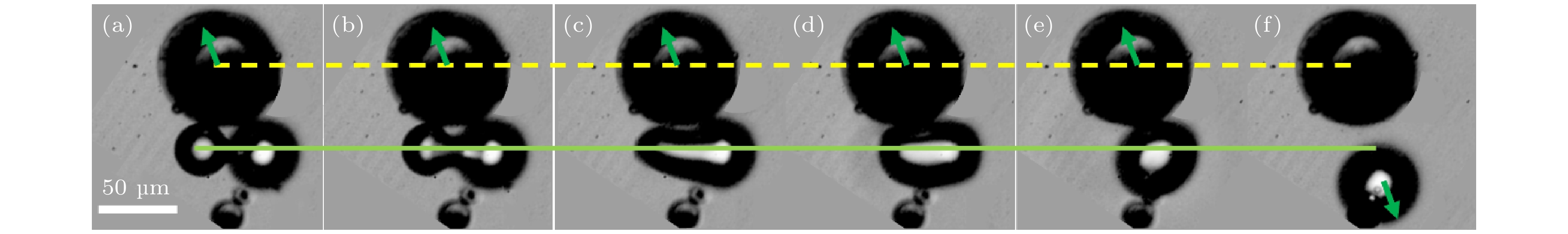
图 6 Rb1 = 7.8 μm, Rb2 = 10.4 μm, Rp = 18.0 μm时, 实验记录气泡聚并驱动颗粒运动序列图 (a) 0; (b) 5 μs; (c) 10 μs; (d) 20 μs; (e) 30 μs; (f) 200 μs
Fig. 6. Experimentally recorded bubble aggregation and driven particle motion sequence diagram at Rb1 = 7.8 μm, Rb2 = 10.4 μm, Rp = 18.0 μm: (a) 0; (b) 5 μs; (c) 10 μs; (d) 20 μs; (e) 30 μs; (f) 200 μs.
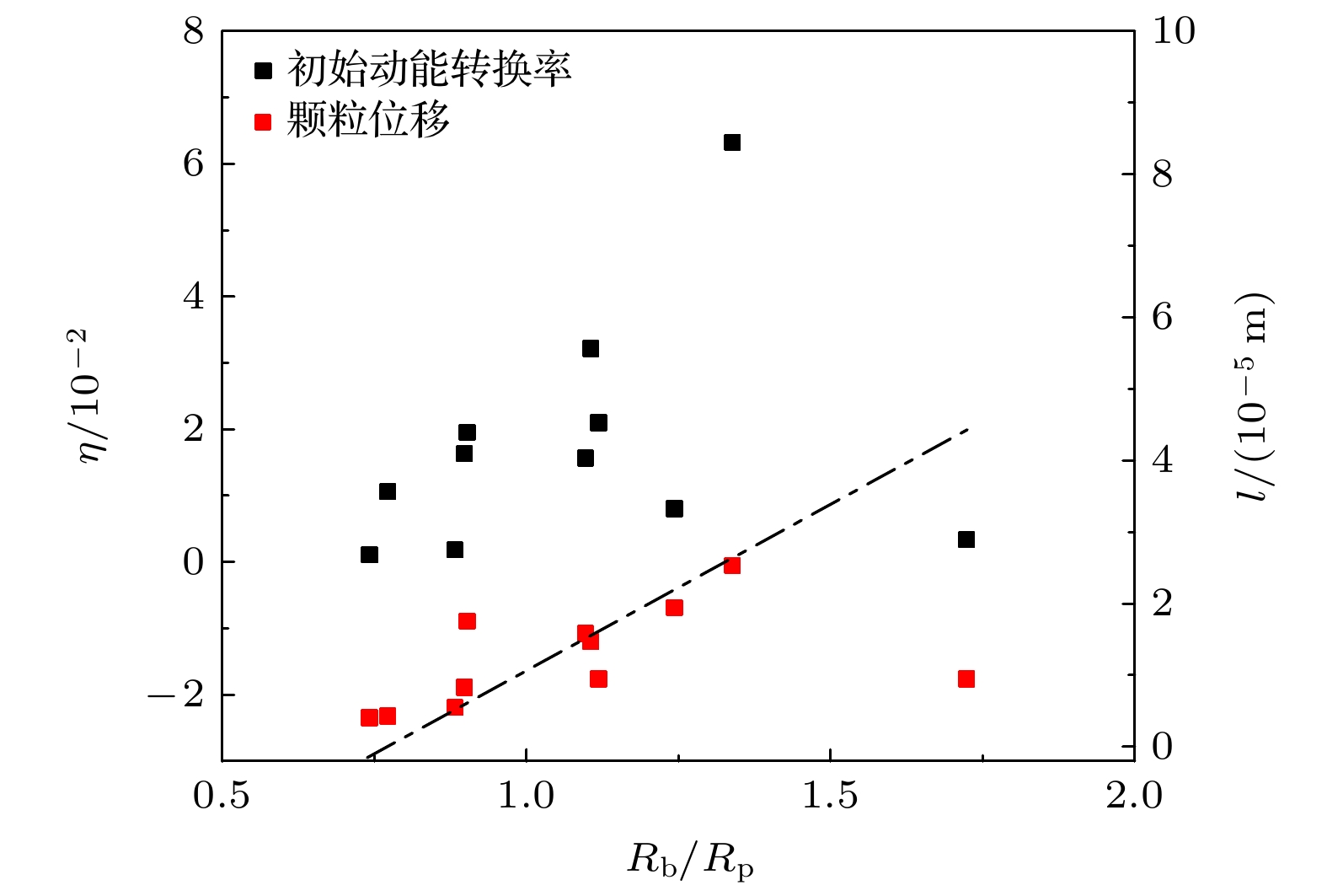
图 7 双气泡聚并驱动颗粒运动的位移、初始动能转换率随气泡与颗粒尺寸比值的变化
Fig. 7. Variation of displacement, initial kinetic energy conversion rate with bubble to particle size ratio for double bubble aggregation and driving particle motion.
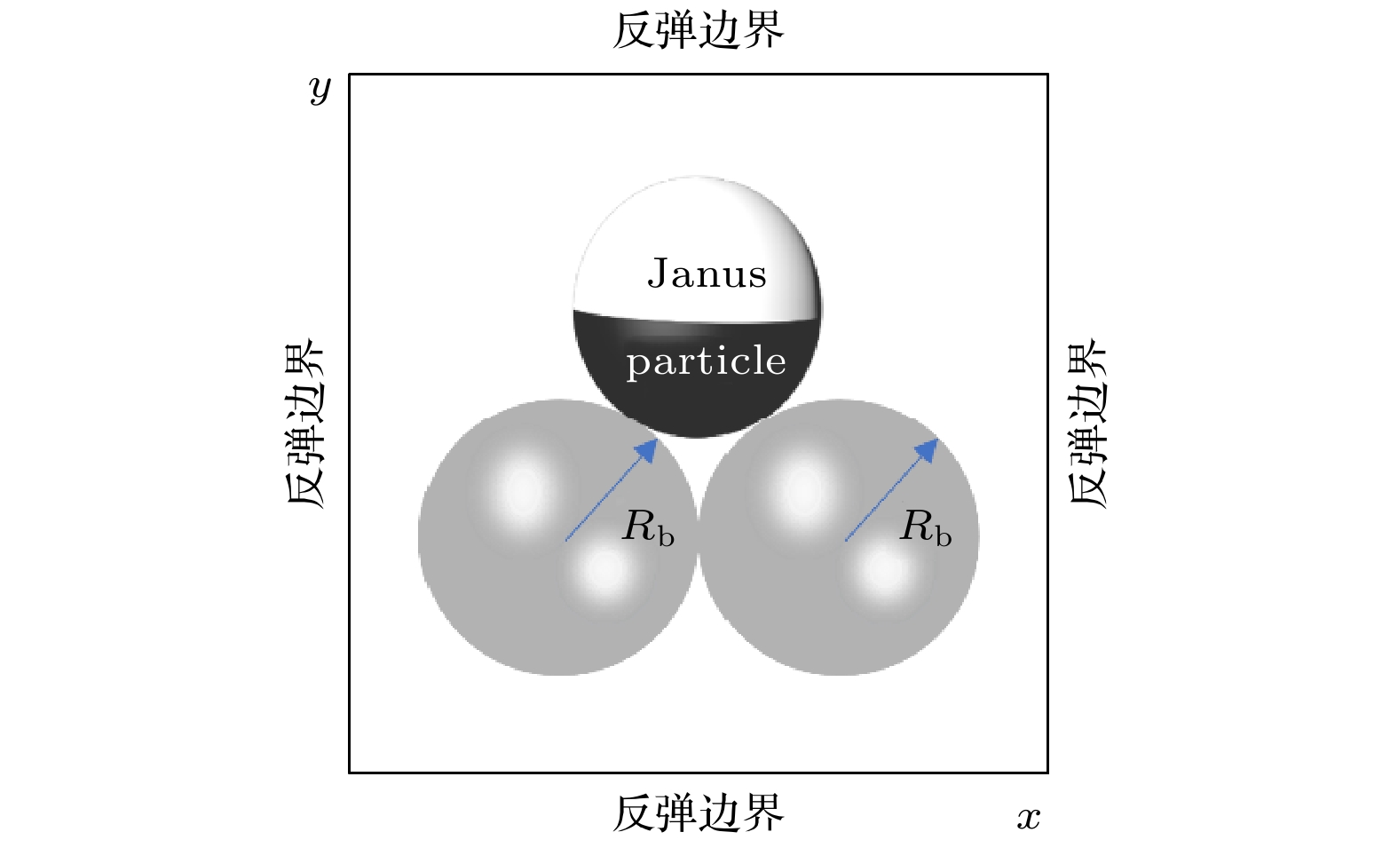
图 8 反弹边界条件液相流场中双气泡数值模拟的计算域及边界条件
Fig. 8. Computational domain and boundary conditions for the numerical simulation of double bubbles in liquid-phase flow field with rebound boundary conditions.

图 9 不同时刻近颗粒气泡聚并演化过程压强及速度场变化 (a) 9.1 μs; (b) 18.3 μs; (c) 36.6 μs; (d) 73.1 μs; (e) 310.8 μs; (f) 914.1 μs
Fig. 9. Variation of pressure and velocity fields during near-particle bubble aggregation and evolution at different moments: (a) 9.1 μs; (b) 18.3 μs; (c) 36.6 μs; (d) 73.1 μs; (e) 310.8 μs; (f) 914.1 μs.

图 10 实验与数值模拟气泡聚并驱动颗粒形态演化对照橙色框内为数值模拟结果(Rb = 20 μm, Rp = 10 μm), 蓝色框内为实验结果(Rb1 = 41 μm, Rb2 = 39 μm, Rp = 34 μm)
Fig. 10. Comparison of experimental and numerical simulations of bubble aggregation-driven particle morphology evolution. The orange box shows the numerical simulation results (Rb = 20 μm, Rp = 10 μm), and the blue box shows the experimental results (Rb1 = 41 μm, Rb2 = 39 μm, Rp = 34 μm).
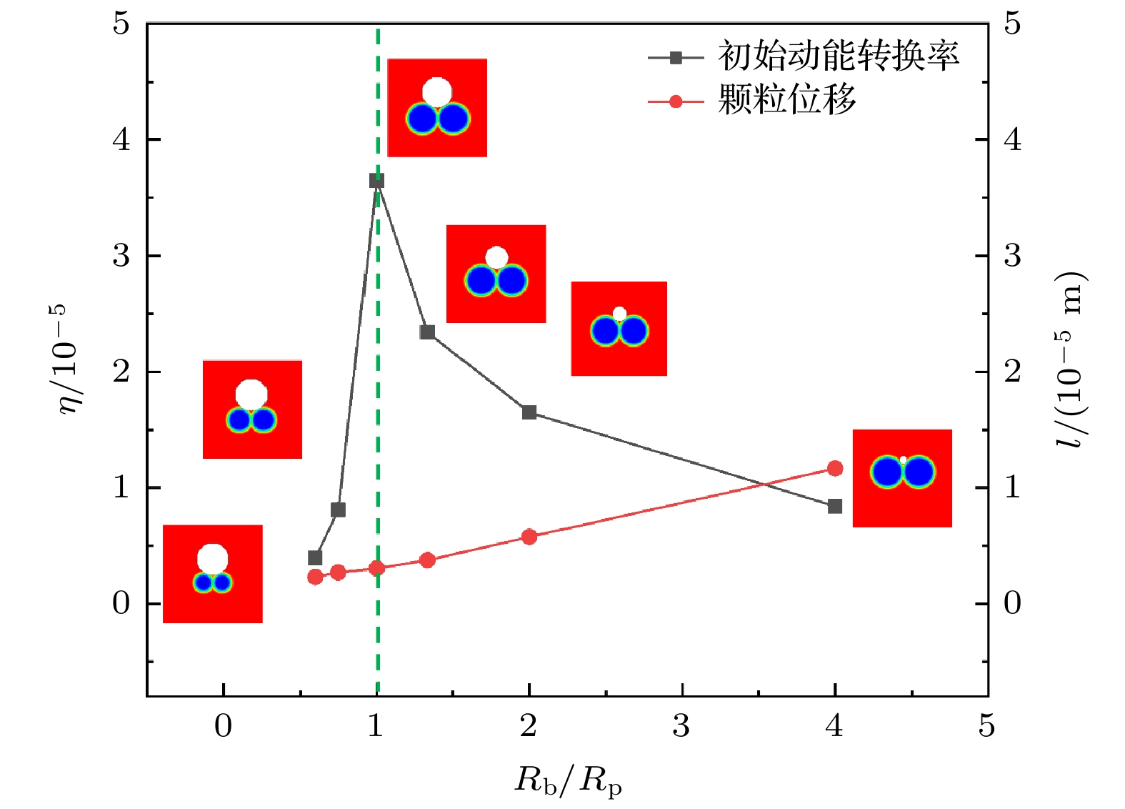
图 11 气泡与颗粒尺寸比与初始动能转换率、颗粒位移之间的关系
Fig. 11. Relationship between bubble to particle size ratio and initial kinetic energy conversion rate, particle displacement.
-
[1] Wang L L, Chen L, Zheng X, Yu Z X, Lü W C, Sheng M J, Wang L N, Nie P C, Li H Y, Guan D S, Cui H H 2022 Small 18 2203872
Google Scholar
[2] 李茂垚, 吴建荣, 郑元义 2020 科学通报 65 4123
Google Scholar
Li M Y, Wu J R, Zheng Y Y 2020 Chin. Sci. Bull. 65 4123
Google Scholar
[3] Li M, Xi N, Wang Y C, Liu L Q 2021 IEEE Trans. Biomed. Eng. 68 130
Google Scholar
[4] Liu L, Wang D W, Rao W 2021 Micromachines 12 280
Google Scholar
[5] Wang W, Duan W T, Ahmed S, Mallouk T E, Sen A 2013 Nano Today 8 531
Google Scholar
[6] Feng Y W, Jia D L, Yue H E, Wang J, Song W P, Li L Q, Zhang A M, Li S, Chang X C, Zhou D K 2023 Small 19 2207565
Google Scholar
[7] Baraban L, Streubel R, Makarov D, Han L Y, Karnaushenko D, Schmidt O G, Cuniberti G 2013 ACS Nano 7 1360
Google Scholar
[8] Pavlick R A, Sengupta S, McFadden T, Zhang H, Sen A 2011 Angew. Chem. Int. Ed. 50 9374
Google Scholar
[9] 郑旭, 崔海航, 李战华 2017 科学通报 62 167
Google Scholar
Zheng X, Cui H H, Li Z H 2017 Chin. Sci. Bull. 62 167
Google Scholar
[10] Wang S J, Wu N 2014 Langmuir 30 3477
Google Scholar
[11] Manjare M, Yang B, Zhao Y P 2012 Phys. Rev. Lett. 109 128305
Google Scholar
[12] 魏梦举, 陈力, 伍涛, 张鸿雁, 崔海航 2017 物理学报 66 164702
Google Scholar
Wei M J, Chen L, Wu T, Zhang H Y, Cui H H 2017 Acta. Phys. Sin. 66 164702
Google Scholar
[13] Wang L L, Chen L, Zhang J, Duan J M, Wang L, Li Z H, Zheng X, Cui H H 2018 Langmuir 34 10426
Google Scholar
[14] Van Leeuwen J L 2010 Science 329 395
Google Scholar
[15] Noblin X, Rojas N O, Westbrook J, Llorens C, Dumais J 2012 Science. 335 1322
Google Scholar
[16] Naeem S, Naeem F, Manjare M, Liao F, Bolaños Quiñones V A, Huang G S, Li Y, Zhang J, Solovev A A, Mei Y F 2019 Appl. Phys. Lett. 114 033701
Google Scholar
[17] 张培赟, 黄高山, 门传玲, 梅永丰 2017 中国科学: 化学 47 14
Google Scholar
Zhang P Y, Huang G S, Men C L, Mei Y F 2017 Sci. Sin. Chem. 47 14
Google Scholar
[18] 孔磊, 牟方志, 姜玉周, 李小丰, 官建国 2017 科学通报 62 107
Google Scholar
Kong L, Mou F Z, Jiang Y Z, Li X F, Guan J G 2017 Chin. Sci. Bull. 62 107
Google Scholar
[19] Wrede P, Medina-Sanchez M, Fomin V M, Schmidt O G 2021 Small 17 2006449
Google Scholar
[20] Wang W, Chiang T Y, Velegol D, Mallouk T E 2013 J. Am. Chem. Soc. 135 10557
Google Scholar
[21] Kupershtokh A L, Medvedev D A, Karpov D I 2009 Comput. Math. Appl 58 965
Google Scholar
[22] Shan X W, Chen H D 1993 Phys. Rev. E 47 1815
Google Scholar
[23] 郭照立, 郑楚光 2009 格子Boltzmann方法的原理及应用 (北京: 科学出版社) 第160—165页
Guo Z L, Zheng C G 2009 Theory and Applications of Lattice Boltzmann Method (Beijing: Science Press) pp160–165 (in Chinese)
[24] Chen L, Yu Y, Lu J H, Hou G X 2014 Int. J. Numer. Methods Fluids 74 439
Google Scholar
[25] Martys N S, Chen H D 1996 Phys. Rev. E 53 743
Google Scholar
[26] Elgeti J, Winkler R G, Gompper G 2015 Rep. Prog. Phys. 78 056601
Google Scholar


 下载:
下载:
计量
- 文章访问数: 1802
- PDF下载量: 51
- 被引次数: 0
