


-
鉴于经锥形玻璃管聚焦的离子束在微纳加工、微区分析以及辐照生物医学等领域具有广阔的应用前景, 本文研究了16 keV C–在不同倾斜角度的锥形玻璃管中输运过程. 实验发现当处于0°倾斜角度时, 出射粒子由核区和晕区构成, 核区是从锥形管后锥孔中直接出射, 未与锥形管内壁之间发生电荷交换, 主要成分为C–离子. 晕区是C–与锥形管内壁发生部分电荷交换作用, 由C–和C0构成. 当倾斜角度为1°时, 出射离子由两部分组成: C0原子束斑和 C–离子束斑, 未出现核区. 出射核区的离子方向始终保持在入射粒子方向, 与锥形管倾斜角度无关. 随着锥形管不断倾斜, 相对透射率不断减小, C0束斑占比增加, C–束斑占比减小. 锥形管对入射离子有聚焦效应. 本实验弥补了低能负离子在锥形管运输过程研究的欠缺, 有助于聚焦离子束的后续开发应用.
The tapered glass capillaries have been widely used in physics, biology, materials. The features of ions transmitted through the insulating tapered glass capillary manifest themselves mainly in the interaction between positive ions and tapered glass capillary, However, the transmission process of negative ions in tapered glass capillary has been studied scarcely so far. In the present study, we measure the properties of 16 keV C– ions transmitted through the tapered glass capillary, such as the two-dimensional spectral distribution, the relative transmission rate, the centroid angle, the charge state purity and the full width at half maximum of the transmitted particles. As the tapered glass capillary tilt angle is equal to 0°, the transmitted particles are composed of three components, i.e. the core, the C– of halo and the C0 of halo. As the tilt angle is 1°, the transmitted particles are composed of two components, i.e. C– and C0. As the tilt angle is >1°, there is no core region, the transmitted particles are composed of two components, i.e. C– and C0. No matter how the tilt angle changes, the centroid angles of core are always along the direction of the incident ions, independent of the tilt angels. And the centroid angles of transmitted C– and C0 are always along the direction of the capillary axis. The transmission processes of 16 keV C– ions in tapered glass capillary with different tilting angles are analyzed qualitatively. When the tilting angle is small (0°–1°), the C– ions are directly traveling straight through the back cone hole of tapered glass capillary, which are mainly composed of C– ions. When the tilt angle is large (>1°), the C– ions cannot directly travel straight through the back cone hole of the tapered glass capillary, and the core region does not appear. Due to the guiding effect of the negative charges deposited on inner wall of tapered glass capillary, the transmitted C– ions are located around the direction of the capillary axis. The tapered glass capillary has a focusing effect on the incident ions. This experiment covers the lack of the studies of low-energy negative ions transmitted through tapered capillary and helps to strengthen the understanding of the transmission process of low-energy ions transmitted through tapered capillary. -
Keywords:
- tapered glass capillary /
- transmission features /
- negative ions
[1] 牛书通 2018 博士学位论文 (兰州: 兰州大学)
Niu S T 2018 Ph. D. Dissertation (Lanzhou: Lanzhou University
[2] Steinbock L J, Otto O, Chimerel C, Gornall J, Keyser U F 2010 Nano Lett. 10 2493
 Google Scholar
[3] Le´tant S E, van Buuren T W, Terminello L J 2004 Nano Lett. 4 1705
Google Scholar
[4] Iwai Y, Ikeda T, Kojima T M, Yamazaki Y, Maeshima K, Imamoto N, Kobayashi T, Nebiki T, Narusawa T, Pokhil G P 2008 Appl. Phys. Lett. 92 023509
Google Scholar
[5] Stolterfoht N, Bremer J H, Hoffmann V, Hellhammer R, Fink D, Petrov A, Sulik B 2002 Phys. Rev. Lett. 88 133201
Google Scholar
[6] Ikeda T, Kanai Y, Kojima T M, Iwai Y, Kambara T, Yamazaki Y, Hoshino M, Nebiki T, Narusawa T 2006 Appl. Phys. Lett. 89 163502
Google Scholar
[7] Cassimi A, Ikeda T, Maunoury L, Zhou C L, Guillous S, Mery A, Lebius H, Benyagoub A, Grygiel C, Khemliche H, Roncin P, Merabet H, Tanis J A 2012 Phys. Rev. A 86 062902
Google Scholar
[8] Stolterfoht N, Hellhammer R, Bundesmann J, Fink D, Kanai Y, Hoshino M, Kambara T, Ikeda T, Yamazaki Y 2007 Phys. Rev. A 76 022712
Google Scholar
[9] Stolterfoht N, Hellhammer R, Fink D, Sulik B, Juhász Z, Bodewits E, Dang H M, Hoekstra R 2009 Phys. Rev. A 79 022901
Google Scholar
[10] Skog P, Zhang H Q, Schuch R 2008 Phys. Rev. Lett. 101 223202
Google Scholar
[11] Zhang H Q, Skog P, Schuch R 2010 Phys. Rev. A 82 052901
Google Scholar
[12] Cassimi A, Maunoury L, Muranaka T, Huber B, Dey K R, Lebius H, Lelièvre D, Ramillon J M, Been T, Ikeda T, Kanai Y, Kojima T M, Iwai Y, Yamazaki Y, Khemliche H , Bundaleski N, Roncin P 2009 Nucl. Instrum. Meth. B 267 674
Google Scholar
[13] Juhász Z, Sulik B, Rácz R, Biri S, Bereczky R J, Tőkési K, Kövér Á, Pálinkás J, Stolterfoht N 2010 Phys. Rev. A 82 062903
Google Scholar
[14] Hasegawa J, Jaiyen S, Polee C, Chankow N, Oguri Y 2011 J. Appl. Phys. 110 044913
Google Scholar
[15] Zhou C L, Simon M, Ikeda T, Guillous S, Iskandar W, Méry A, Rangama J, Lebius H, Benyagoub A, Grygiel C, Müller A, Döbeli M, Tanis J A, Cassimi A 2013 Phys. Rev. A 88 050901
Google Scholar
[16] Gruber E, Kowarik G, Ladening F, Waclawek J P, Aumayr F, Bereczky R J, Tőkési K, Gunacker P, Schweigler T, Lemell C, Burgdörfer J 2012 Phys. Rev. A 86 062901
Google Scholar
[17] Stolterfoht N, Gruber E, Allinger P, Wampl S, Wang Y Y, Simon M J, Aumayr F 2015 Phys. Rev. A 91 032705
[18] Simon M J, Zhou C L, Döbeli M, Cassim A, Monnet I, Méry A , Grygiel C, Guillous S, Madi T, Benyagoub A, Lebius H, Müller A M, Shiromaru H, Synal H A 2014 Nucl. Instrum. Methods Phys. Res., Sect. B 330 11
Google Scholar
[19] Nakayama R, Tona M, Nakamura N, Watanabe H, Yoshiyasu N, Yamada C, Yamazaki A, Ohtani S, Sakurai M 2009 Nucl. Instrum. Methods. Phys. Res., Sect. B 267 2381
Google Scholar
[20] Nebiki T, Yamamoto T, Narusawa T, Breese B H, Teo E J, Watt F 2003 J. Vac. Sci. Technol. 21 1671
[21] Liu S D, Wang Y Y, Zhao Y T, Zhou X M, Cheng R, Lei Y, Sun Y B, Ren J R, Duan J L, Liu J, Xu H S, Xiao G Q 2005 Phys. Rev. A 91 012714
[22] Pan P, Niu S T, Song H Y, Chen X M, Shao J X 2019 Nucl. Instrum. Methods Phys. Res. , Sect. B 450 332
Google Scholar
[23] Song H Y, Yang Z S, Yu L F, Zhou D J, Zhou D W, Shao J X, Yang A X 2020 Eur. Phys. J. D 74 208
Google Scholar
-
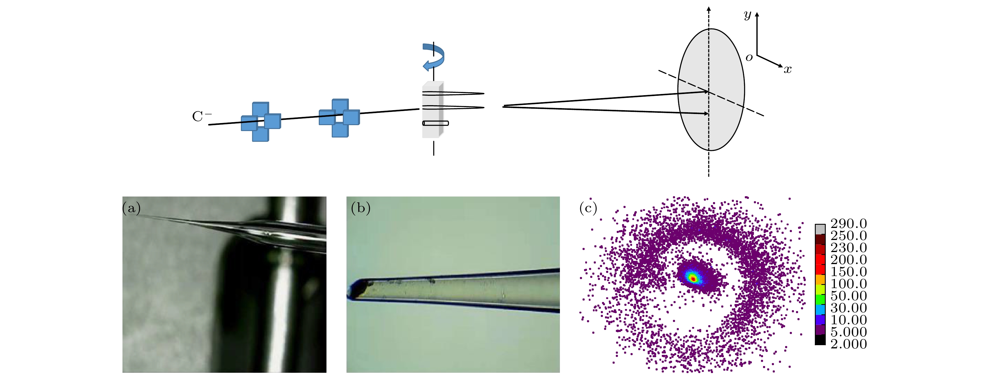
图 1 实验装置示意图 (a) 使用锥形管轮廓图, 入口直径为580 μm; (b) 锥形出口情况, 直径为23 μm; (c) 倾斜角度为0°时的二维谱图
Fig. 1. The schematic view of the setup for the ion transmission experiments: (a) The profile of tapered glass capillary with an inlet diameter of 580 μm and (b) the outlet with a diameter of 23 μm; (c) the typical two-dimensional spectrum of transmitted particles with 16 keV incident energy and with a tilt angel of 0°.
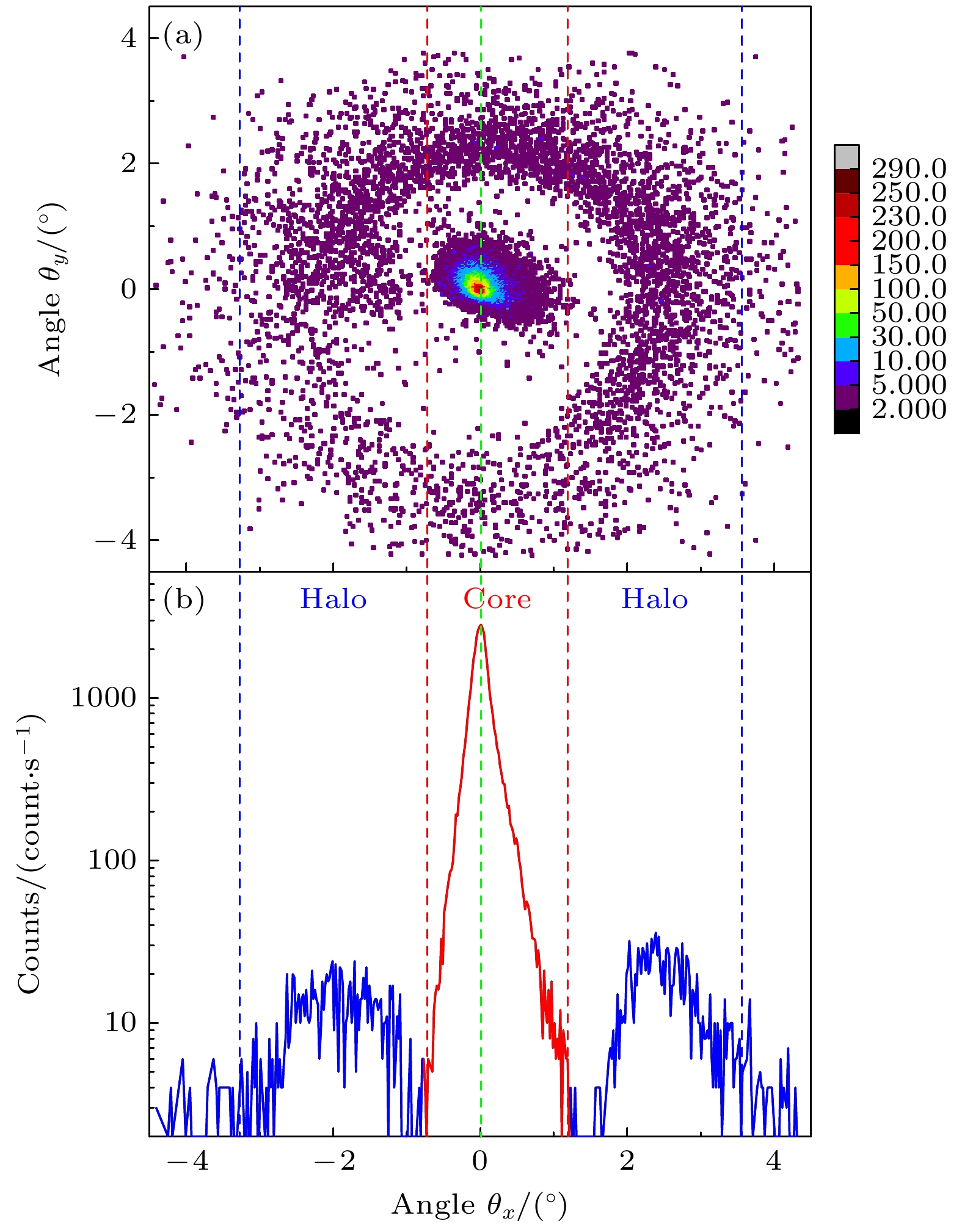
图 2 16 keV C–入射处于0°倾斜角的锥形管, 未加偏转电压时出射粒子的二维分布谱图 (a)以及在X轴方向上的投影分布情况(b)
Fig. 2. The typical two-dimensional spectrum (a) and the projections in the X-axis direction of the transmitted particles (b) after 16 keV C– transmitted through tapered glass capillary with a tilt angle of 0° with the 0 V defection bias.

图 3 16 keV C–入射处于0°倾斜角的锥形管, 偏转电压为300 V时出射粒子的二维分布谱图(a)以及在Y轴方向上的投影分布情况(b)
Fig. 3. The typical two-dimensional spectrum (a) and the projections in the Y-axis direction of the transmitted particles (b) after 16 keV C– transmitted through tapered glass capillary with a tilt angle of 0°with the 300 V defection bias.
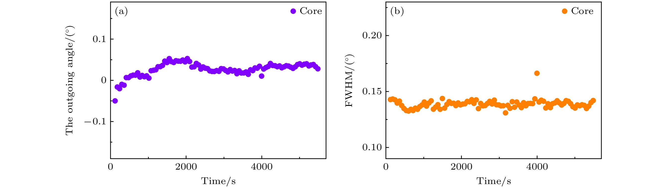
图 4 16 keV C–入射处于0°倾斜角的锥形管时, 出射离子core区域中心角度分布(a)和半高宽(b)的演化情况
Fig. 4. The evolution of the outgoing angle of core (a) and the FWHM of the transmitted particles (b) for 16 keV C– transmitted through tapered glass capillary at the tilt angle of 0°.
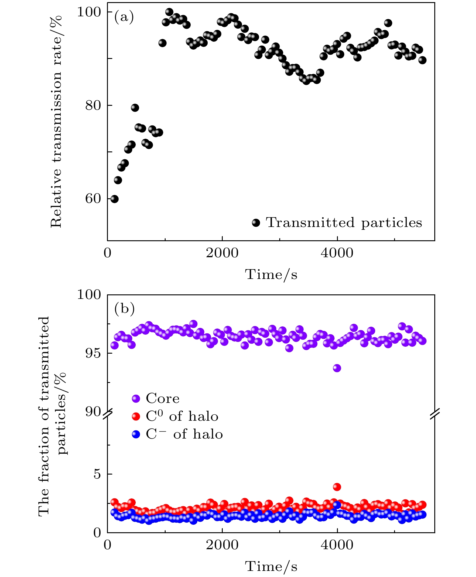
图 5 16 keV C–入射处于0°倾斜角的锥形管时, 相对透射率(a)和C–, C0占比(b)的演化情况
Fig. 5. The evolution of the relatively transmission rate (a) and the fraction of the transmitted particles (b) for 16 keV C– transmitted through tapered glass capillary at the tilt angle of 0°.

图 6 16 keV C–入射处于1°倾斜角的锥形管时, 偏转电压为200 V时出射粒子的二维分布谱图(a)以及在Y轴方向上的投影分布情况(b). 其中紫线表示锥形管倾斜方向, 为1°, 红线表示出射C0在Y轴中心出射方向, 蓝线表示C– 在Y轴中心出射方向
Fig. 6. The typical two-dimensional spectrum (a) and the projections in the Y-axis direction of the transmitted particles (b) after 16 keV C– transmitted through tapered glass capillary with a tilt angle of 1° with the 200 V defection bias. The purple line indicates the tilt angle of the tapered glass capillary, the red line indicates the center direction of C0 ions, and the blue line indicates the center direction of C– ions.
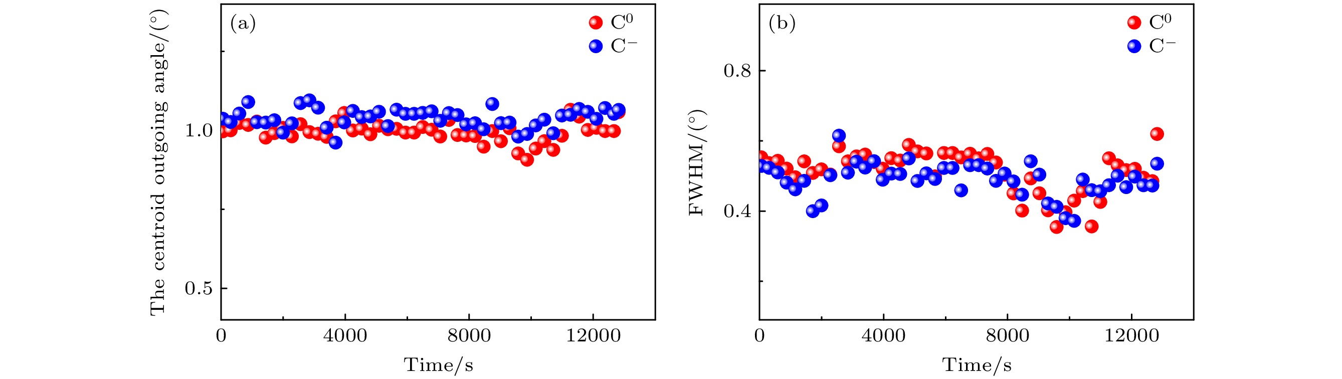
图 7 16 keV C–入射处于1°倾斜角的锥形管时, 中心出射角度方向(a)和半高宽(b)的演化情况
Fig. 7. The evolution of the outgoing angle (a) and the FWHM of the transmitted particles (b) for 16 keV C– transmitted through tapered glass capillary at the tilt angle of 1°.
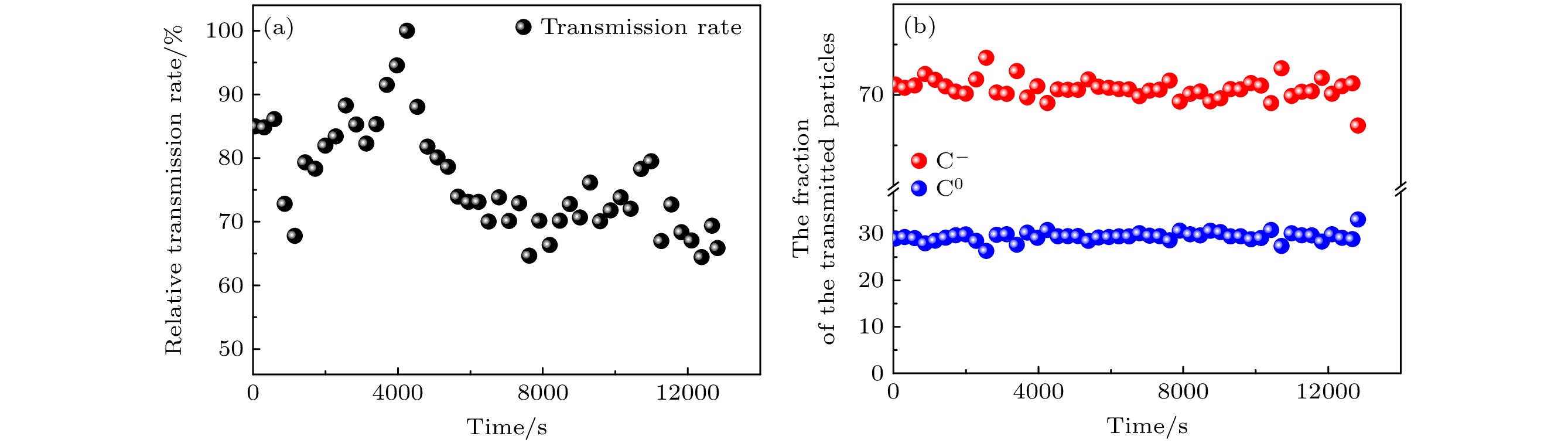
图 8 16 keV C–入射处于1°倾斜角的锥形管时, 相对透射率(a)和C–, C0占比(b)随的演化情况
Fig. 8. The evolution of the relatively transmission rate (a) and the fraction of the transmitted particles (b) for 16 keV C– transmitted through tapered glass capillary at the tilt angle of 0°.

图 9 16 keV C–入射处于不同倾斜角的锥形管时, 中心出射角度方向(a)和半高宽(b)随倾斜角度演化
Fig. 9. The evolution of the outgoing angle (a) and the FWHM of the transmitted particles (b) at various tilt angles for 16 keV C– transmitted through tapered glass capillary
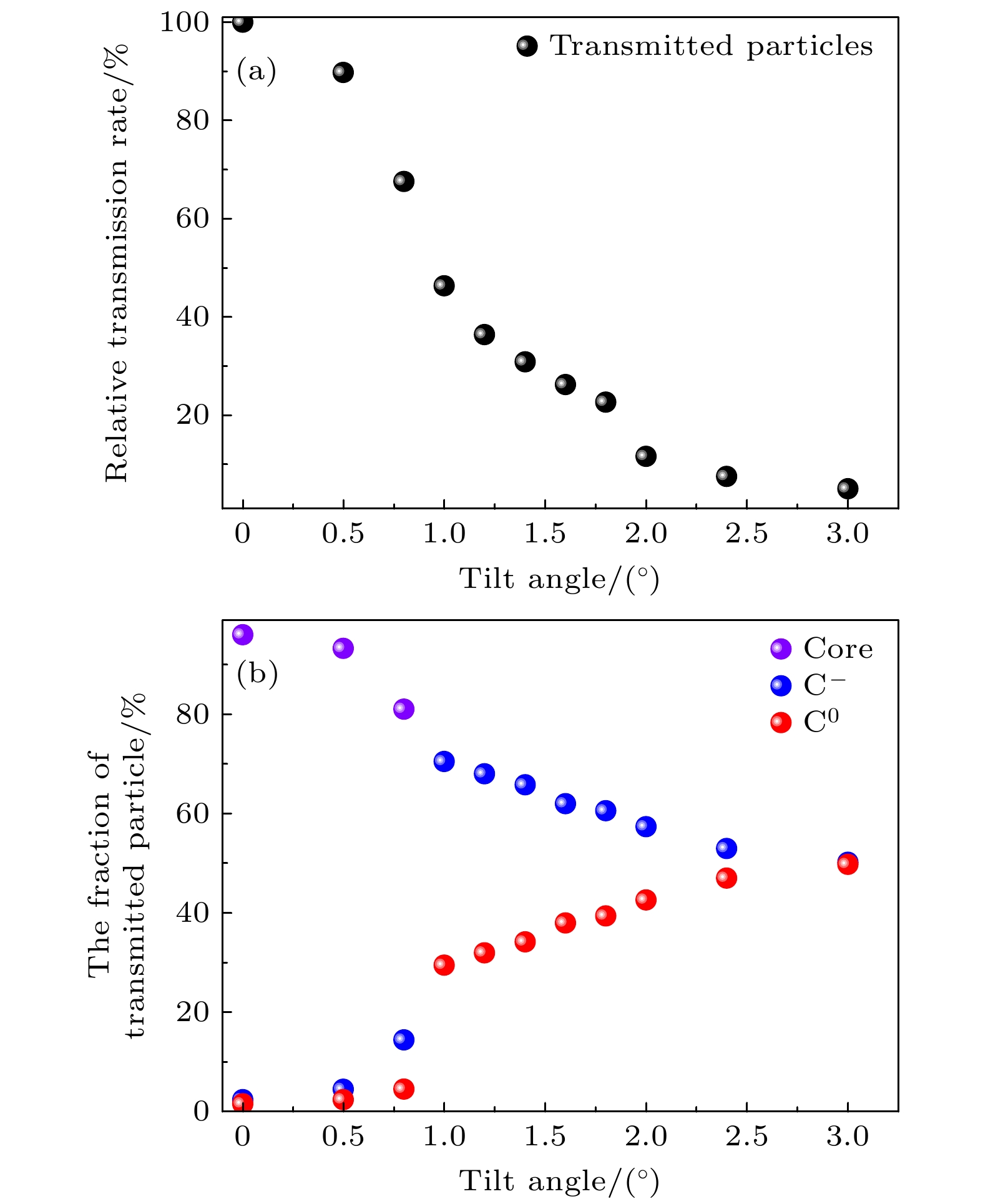
图 10 16 keV C– 离子入射处于不同倾斜角的锥形管时, 相对透射率(a)和C–, C0占比(b)随锥形管倾斜角度的演化
Fig. 10. The evolution of the relatively transmission rate (a) and the fraction of the transmitted particles (b) at various tilt angles for 16 keV C– transmitted through tapered glass capillary.
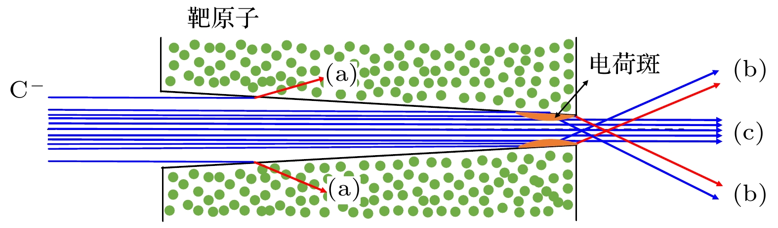
图 11 16 keV C–入射处于0°倾斜角的锥形管时, 入射离子在锥形管中的输运示意图
Fig. 11. Simulated trajectories of transmitted particles for 16 keV C– transmitted through tapered glass capillary at the tilt angle of 0°.
-
[1] 牛书通 2018 博士学位论文 (兰州: 兰州大学)
Niu S T 2018 Ph. D. Dissertation (Lanzhou: Lanzhou University
[2] Steinbock L J, Otto O, Chimerel C, Gornall J, Keyser U F 2010 Nano Lett. 10 2493
Google Scholar
[3] Le´tant S E, van Buuren T W, Terminello L J 2004 Nano Lett. 4 1705
Google Scholar
[4] Iwai Y, Ikeda T, Kojima T M, Yamazaki Y, Maeshima K, Imamoto N, Kobayashi T, Nebiki T, Narusawa T, Pokhil G P 2008 Appl. Phys. Lett. 92 023509
Google Scholar
[5] Stolterfoht N, Bremer J H, Hoffmann V, Hellhammer R, Fink D, Petrov A, Sulik B 2002 Phys. Rev. Lett. 88 133201
Google Scholar
[6] Ikeda T, Kanai Y, Kojima T M, Iwai Y, Kambara T, Yamazaki Y, Hoshino M, Nebiki T, Narusawa T 2006 Appl. Phys. Lett. 89 163502
Google Scholar
[7] Cassimi A, Ikeda T, Maunoury L, Zhou C L, Guillous S, Mery A, Lebius H, Benyagoub A, Grygiel C, Khemliche H, Roncin P, Merabet H, Tanis J A 2012 Phys. Rev. A 86 062902
Google Scholar
[8] Stolterfoht N, Hellhammer R, Bundesmann J, Fink D, Kanai Y, Hoshino M, Kambara T, Ikeda T, Yamazaki Y 2007 Phys. Rev. A 76 022712
Google Scholar
[9] Stolterfoht N, Hellhammer R, Fink D, Sulik B, Juhász Z, Bodewits E, Dang H M, Hoekstra R 2009 Phys. Rev. A 79 022901
Google Scholar
[10] Skog P, Zhang H Q, Schuch R 2008 Phys. Rev. Lett. 101 223202
Google Scholar
[11] Zhang H Q, Skog P, Schuch R 2010 Phys. Rev. A 82 052901
Google Scholar
[12] Cassimi A, Maunoury L, Muranaka T, Huber B, Dey K R, Lebius H, Lelièvre D, Ramillon J M, Been T, Ikeda T, Kanai Y, Kojima T M, Iwai Y, Yamazaki Y, Khemliche H , Bundaleski N, Roncin P 2009 Nucl. Instrum. Meth. B 267 674
Google Scholar
[13] Juhász Z, Sulik B, Rácz R, Biri S, Bereczky R J, Tőkési K, Kövér Á, Pálinkás J, Stolterfoht N 2010 Phys. Rev. A 82 062903
Google Scholar
[14] Hasegawa J, Jaiyen S, Polee C, Chankow N, Oguri Y 2011 J. Appl. Phys. 110 044913
Google Scholar
[15] Zhou C L, Simon M, Ikeda T, Guillous S, Iskandar W, Méry A, Rangama J, Lebius H, Benyagoub A, Grygiel C, Müller A, Döbeli M, Tanis J A, Cassimi A 2013 Phys. Rev. A 88 050901
Google Scholar
[16] Gruber E, Kowarik G, Ladening F, Waclawek J P, Aumayr F, Bereczky R J, Tőkési K, Gunacker P, Schweigler T, Lemell C, Burgdörfer J 2012 Phys. Rev. A 86 062901
Google Scholar
[17] Stolterfoht N, Gruber E, Allinger P, Wampl S, Wang Y Y, Simon M J, Aumayr F 2015 Phys. Rev. A 91 032705
[18] Simon M J, Zhou C L, Döbeli M, Cassim A, Monnet I, Méry A , Grygiel C, Guillous S, Madi T, Benyagoub A, Lebius H, Müller A M, Shiromaru H, Synal H A 2014 Nucl. Instrum. Methods Phys. Res., Sect. B 330 11
Google Scholar
[19] Nakayama R, Tona M, Nakamura N, Watanabe H, Yoshiyasu N, Yamada C, Yamazaki A, Ohtani S, Sakurai M 2009 Nucl. Instrum. Methods. Phys. Res., Sect. B 267 2381
Google Scholar
[20] Nebiki T, Yamamoto T, Narusawa T, Breese B H, Teo E J, Watt F 2003 J. Vac. Sci. Technol. 21 1671
[21] Liu S D, Wang Y Y, Zhao Y T, Zhou X M, Cheng R, Lei Y, Sun Y B, Ren J R, Duan J L, Liu J, Xu H S, Xiao G Q 2005 Phys. Rev. A 91 012714
[22] Pan P, Niu S T, Song H Y, Chen X M, Shao J X 2019 Nucl. Instrum. Methods Phys. Res. , Sect. B 450 332
Google Scholar
[23] Song H Y, Yang Z S, Yu L F, Zhou D J, Zhou D W, Shao J X, Yang A X 2020 Eur. Phys. J. D 74 208
Google Scholar

 下载:
下载:

计量
- 文章访问数: 630
- PDF下载量: 32
- 被引次数: 0
