


-
忆容器是一种具有记忆性的非线性电容, 为研究忆容器的电路特性, 提出了一种压控型忆容器的二次曲线模型, 利用电流反馈型运放等器件构建了能够动态模拟忆容器q-v特性的仿真器. 通过仿真和实验观测到忆容器的滞回曲线, 以及随外加激励频率增加而收缩的特性. 分析了周期性激励信号的参数对忆容值取值范围的影响, 并对忆容器的非易失性和平衡点的稳定性进行了研究. 基于该忆容仿真器设计了一种多谐振荡器, 分析了振荡器的工作原理, 对振荡器的输出电压、忆容器的端电压、忆容器的磁通和电荷, 以及忆容器的滞回曲线进行了测试. 通过实验中观测到的各种振荡波形, 分析了振荡器的频率、占空比以及忆容器的非线性特性随电路参数变化的规律.Memcapacitor is a kind of non-linear capacitor with memory capability. In order to study the electrical characteristics of memcapacitor and its application circuit, a quadratic model of voltage-controlled memcapacitor is proposed, and an emulator which can dynamically simulate the q–v characteristics of the memcapacitor is designed by using a current feedback operational amplifier, multiplier and other devices. The emulator does not need to be converted by any memristor or meminductor. It can work in floating or grounding state. The constitutive relation of the memcapacitor emulator is deduced, and the circuit parameters of the emulator are designed. Based on the simulations and experimental results, the pinched hysteresis loop and its dependence on frequency are verified. In addition, the range of the memcapacitance under periodic signal excitation is discussed and the influence of periodic excitation signal on the range of memcapacitance is analyzed. Through observing the dynamic route map (DRM) of the memcapacitor, its nonvolatility and the stability of the equilibrium point are also studied. The simulation results show that the memcapacitor can exhibit infinite stable equilibrium points and can be stabilized at any equilibrium state. With respect to pulse excitation signal, the effects of pulse width and amplitude on the switching on or off of the state for the memcapacitor is analyzed, and the corresponding switching method and rule are proposed. This characteristic of memcapacitor makes it have potential applications in non-volatile memory, neural network and other fields. Based on the proposed memcapacitor model, a multivibrator circuit is designed. Then, the working principle of the oscillator is analyzed, and the equation of oscillator is derived. The output voltage of the oscillator, the terminal voltage of the memcapacitor, the flux and the charge of the memcapacitor, and the pinched hysteretic curve of the memcapacitor during oscillation are tested experimentally. Besides, various oscillation waveforms whose frequency and duty cycle are different are observed and further analyzed. The circuit structure of the memcapacitor multivibrator designed in this paper is very simple. It can generate stable rectangular wave signals with controllable frequency and duty cycle, and it can be used in testing signal or driving the device.
-
Keywords:
- memcapacitor /
- non-volatility /
- multivibrator
[1] Di Ventra M, Pershin Y V, Chua L O 2009 Proc. IEEE 97 1717
 Google Scholar
[2] Wang G Y, Cai B Z, Jin P P, Hu T L 2017 Chin. Phys. B 25 010503
[3] Pershin Y V, Di Ventra M 2012 Proc. IEEE 100 2071
Google Scholar
[4] Driscoll T, Quinn J, Klein S, Kim H T, Kim B J 2010 Appl. Phys. Lett. 97 093502
Google Scholar
[5] Li Y F, Yang C Y, Yu Y B 2017 Proceedings of the 36th Chinese Control Conference Dalian, China, July 26−28, 2017 p5110
[6] Flak J, Lehtonen E, Laiho M, Rantala A, Prunnila M, Haatainen T 2014 Semicond. Sci. Technol. 29 104012
Google Scholar
[7] Noh Y J, Baek Y J, Hu Q, Kang C J, Choi Y J, Lee H H 2015 IEEE Trans. Nanotechnol. 14 798
Google Scholar
[8] Yuan F, Wang G Y, Shen Y R, Wang X Y 2016 Nonlinear Dyn. 86 37
Google Scholar
[9] Fouda M E, Khatib M A, Radwan A G 2013 25th International Conference on Microelectronics Beirut, Lebanon, December 15−18, 2013 p978
[10] Biolek D, Biolek Z, Biolkova V 2010 Electron. Lett. 46 520
Google Scholar
[11] Biolek D, Biolkova V, Kolka Z 2010 IEEE Asia Pacific Conference on Circuits and Systems Kuala, Lumpur, Malaysia, December 6−9, 2010 p800
[12] Yu D S, Liang Y, Chen H 2013 IEEE Trans. Circuits Syst. II, Exp. Briefs 60 207
Google Scholar
[13] Yu D S, Liang Y, Herbert H C I 2014 IEEE Trans. Circuits Syst. II, Exp. Briefs 61 758
Google Scholar
[14] Yu D S, Zhou Z, Herbert H C I 2016 IEEE Trans. Circuits Syst. II, Exp. Briefs 63 1101
Google Scholar
[15] 李志军, 向林波, 肖文润 2017 电子与信息学报 39 1626
Li Z J, Xiang L B, Xiao W R 2017 J. Electron. Inform. Technol. 39 1626
[16] Chua L O 2015 Radioengineering 24 319
Google Scholar
[17] Jin P P, Wang G Y, Herbert H C I 2018 IEEE Trans. Circuits Syst. II, Exp. Briefs 65 246
Google Scholar
[18] Chua L O 2018 Appl. Phys. A-Mater. 124 563
Google Scholar
[19] Yu D S, Herbert H C I 2014 IEEE Trans. Circuits Syst. I, Reg. Papers 61 2888
Google Scholar
[20] Pershin Y V, Massimiliano D V 2011 Electron. Lett. 47 243
Google Scholar
-

图 2 正弦交流电激励下忆容器
${C_{\rm{m}}}$ 、${v_{\rm C}}$ 和$\phi $ 的时域波形(a)${C_{\rm{m}}}$ ; (b)${v_C}$ ; (c)$\phi $ Fig. 2. Time domain waveforms of Cm, vC and flux under periodic excitation signal: (a)
${C_{\rm{m}}}$ ; (b)${v_C}$ ; (c)$\phi $ .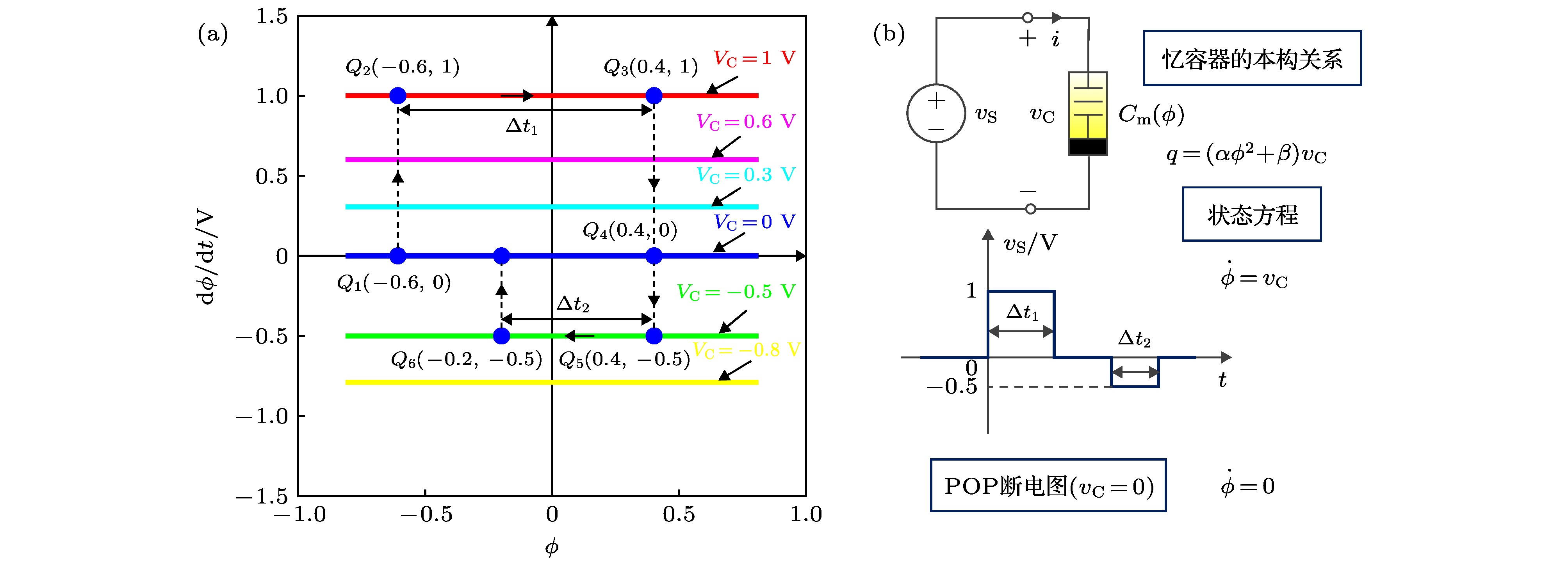
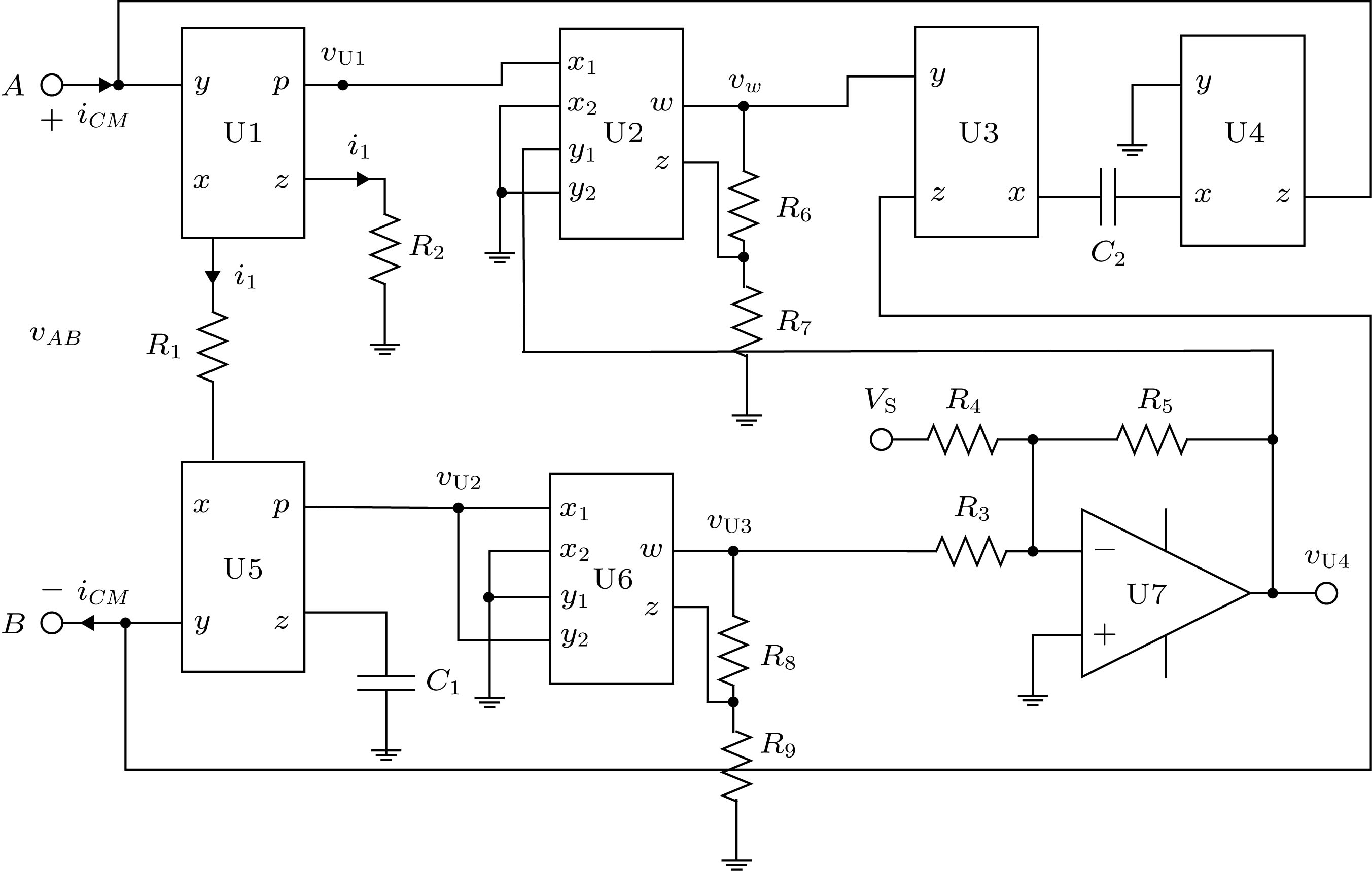
图 3 忆容器的动态路径图(
${\rm{d}}\phi /{\rm{d}}t \text- \phi $ ) (a)动态路径图; (b)忆容器电路和Vs波形Fig. 3. Dynamic path map of memcapacitor (
${\rm{d}}\phi /{\rm{d}}t \text- \phi $ ): (a)Dynamic path map ; (b) Memcapacitor circuit and Vs waveform.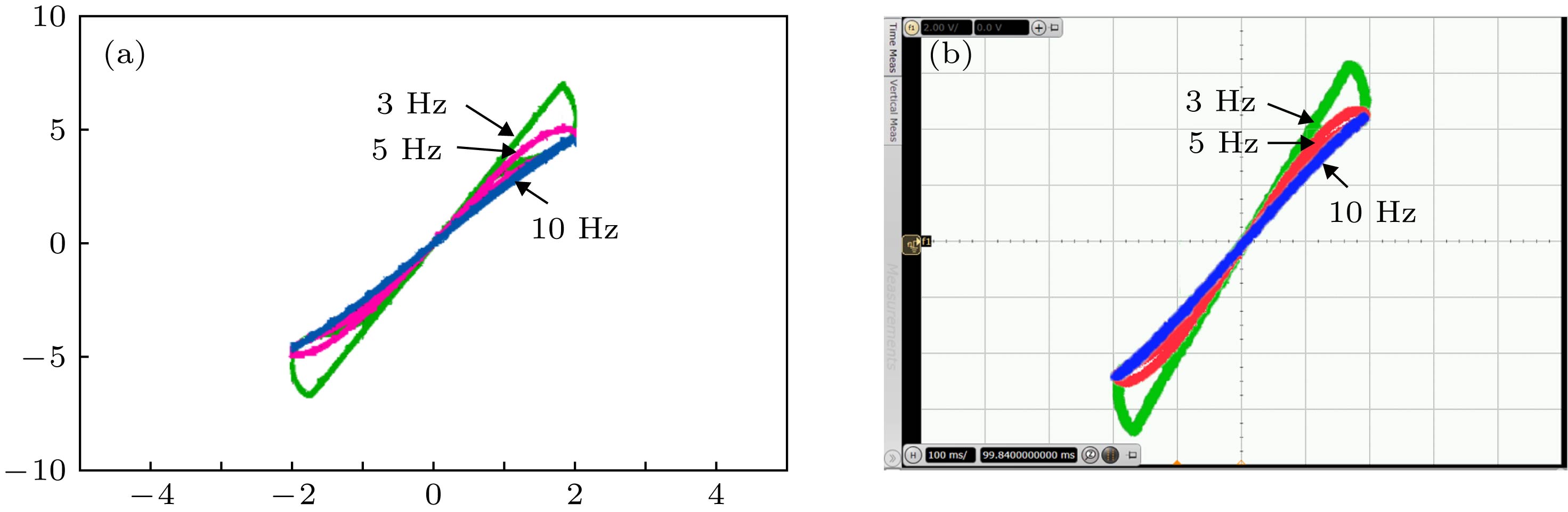
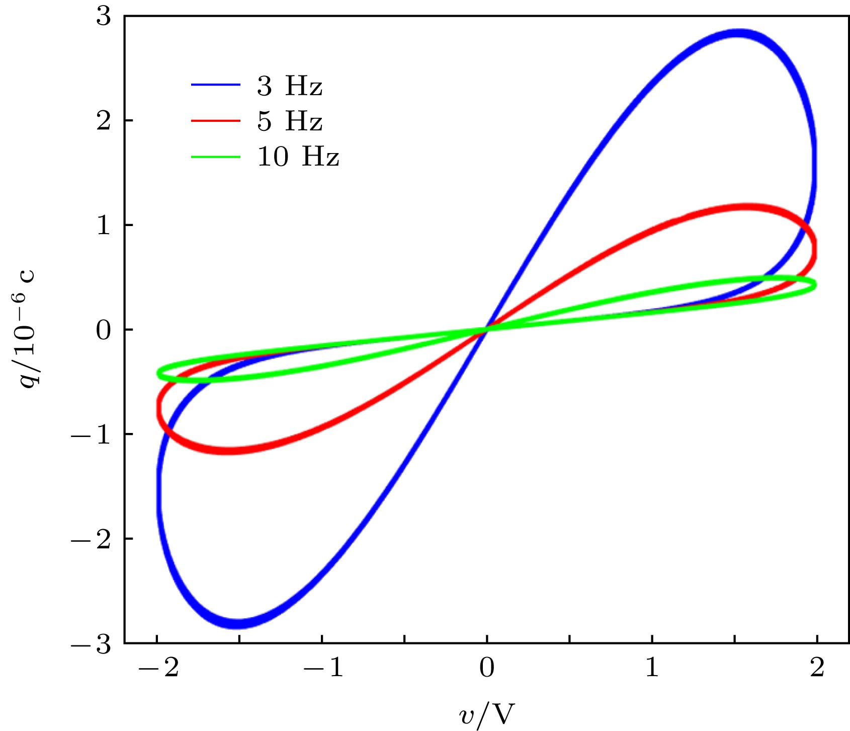
图 5 忆容器仿真器的
$q \text- v$ 曲线(横坐标和纵坐标分别对应于${v_{AB}}$ 和${v_w}$ ) (a)仿真电路的测试结果图, 纵坐标显示范围[–10, 10] V, 横坐标显示范围[–5, 5] V; (b)硬件实验电路的测试结果, 横坐标和纵坐标显示分别为1 V/格和2 V/格Fig. 5. q-v pinched hysteresis loops of the memcapacitor simulator: the abscissa and ordinate correspond to
${v_{AB}}$ and${v_w}$ , respectively: (a) Results of circuit simulation.The display range of ordinates is [–10, 10] V, and the display range of abscissa is [–5, 5] V; (b) result of hardware experiment circuit; the abscissa and ordinates are shown as 1 V/lattice and 2 V/lattice, respectively.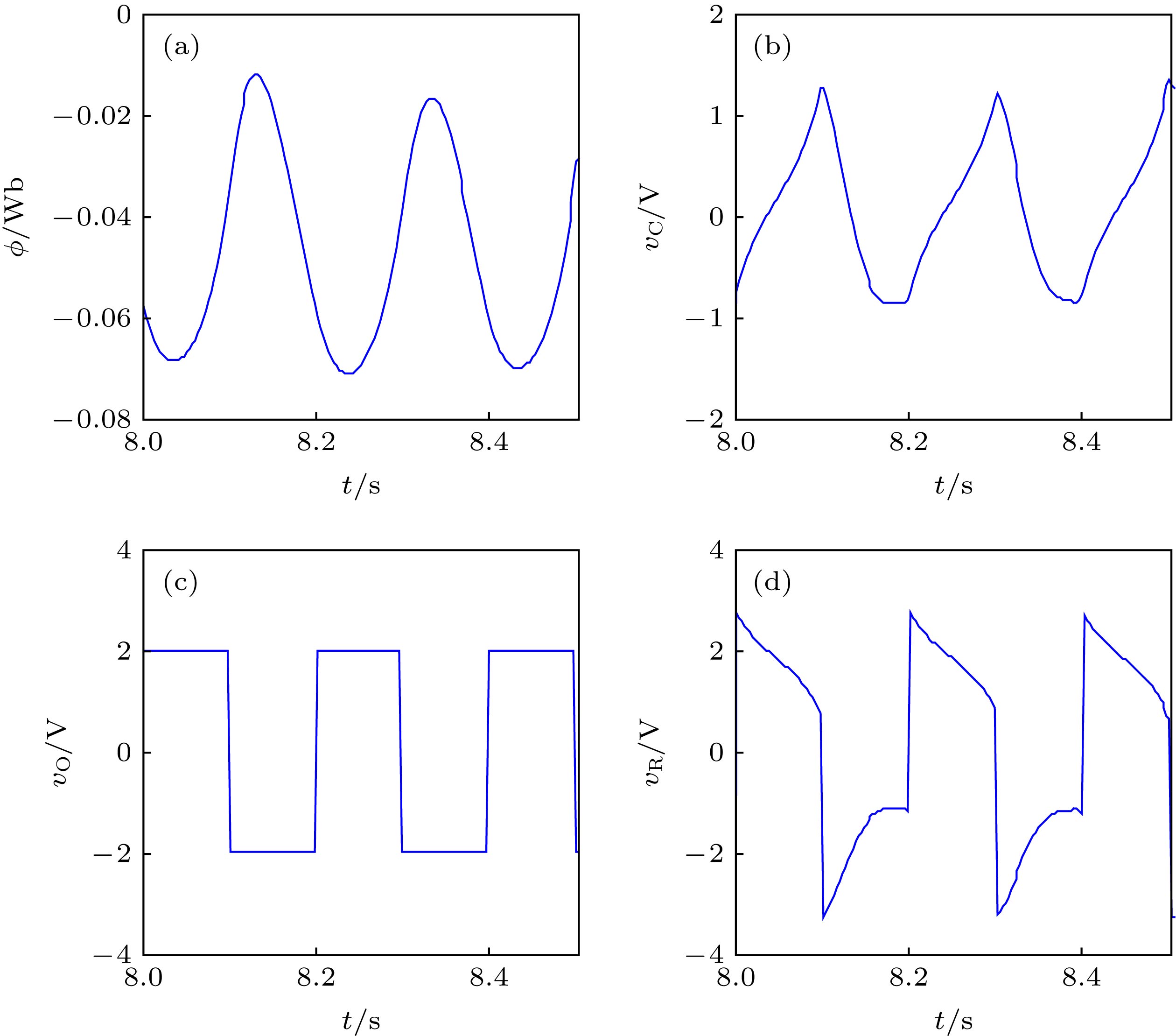
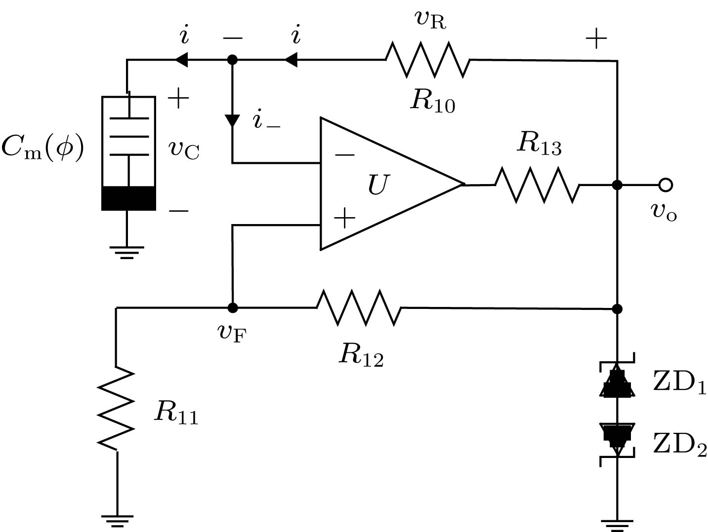
图 7
${R_{10}}{C_{\rm{m}}}$ 回路中忆容器的磁通、电压和${v_R}$ 的时域波形 (a)$\phi $ ; (b) vC; (c) vO; (d) vRFig. 7. In R10Cm circuit, the time-domain waveforms of flux and voltage of the memcapacitor and voltage vR: (a)
$\phi $ ; (b) vC; (c) vO; (d) vR.
图 8 忆容器多谐振荡器仿真电路波形(
${v_{\rm{O}}}$ 、${v_w}$ 和${v_C}$ 纵坐标的显示范围均为$[-5.0, 5.0]\;{\rm{V}}$ ,${v_{{\rm{U}}3}}$ 纵坐标的显示范围是$[ - 2.0, 2.0]\;{\rm{V}}$ )Fig. 8. Simulation waveforms of memcapacitor multivibrator: The display range of vertical coordinates
${v_{\rm{O}}}$ 、${v_w}$ and${v_C}$ are all$[ - 5.0, 5.0]\;{\rm{V}}$ , but the display range of vertical coordinates of${v_{{\rm{U}}3}}$ is$[ - 2.0, 2.0]\;{\rm{V}}$ .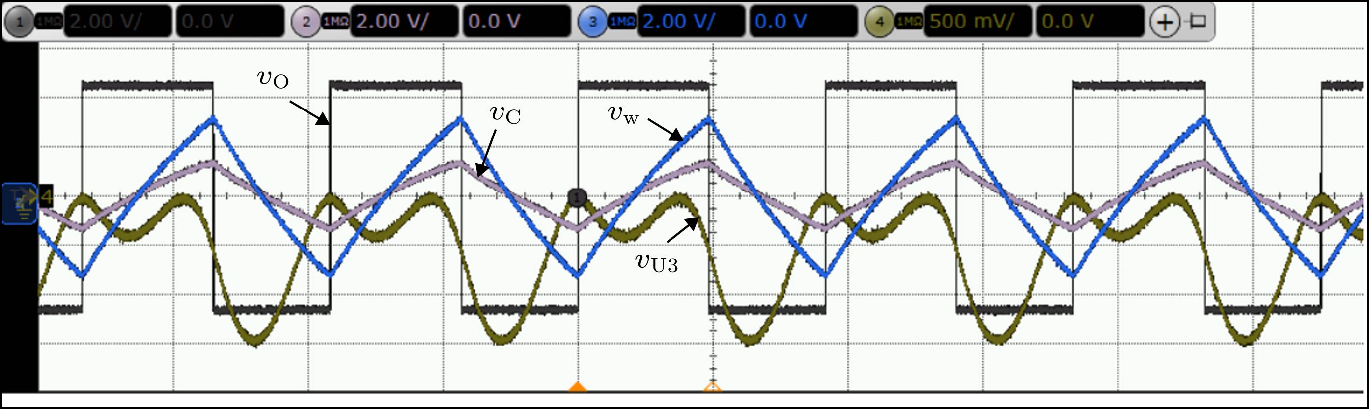
图 9 硬件电路实测振荡波形(
${v_{\rm{o}}}$ 、${v_C}$ 和${v_w}$ 幅值均为2 V/格,${v_{{\rm{U}}3}}$ 为500 mV/格, 时间轴均为100 ms/格)Fig. 9. Measurement of oscillating waveforms in hardware circuit: (The vertical axes of
${v_{\rm{o}}}$ ,${v_C}$ and${v_w}$ are both 2 V/lattice, the vertical axes of${v_{{\rm{U}}3}}$ is 500 mV/lattice, The horizontal axes of all voltages are 100 ms/lattice).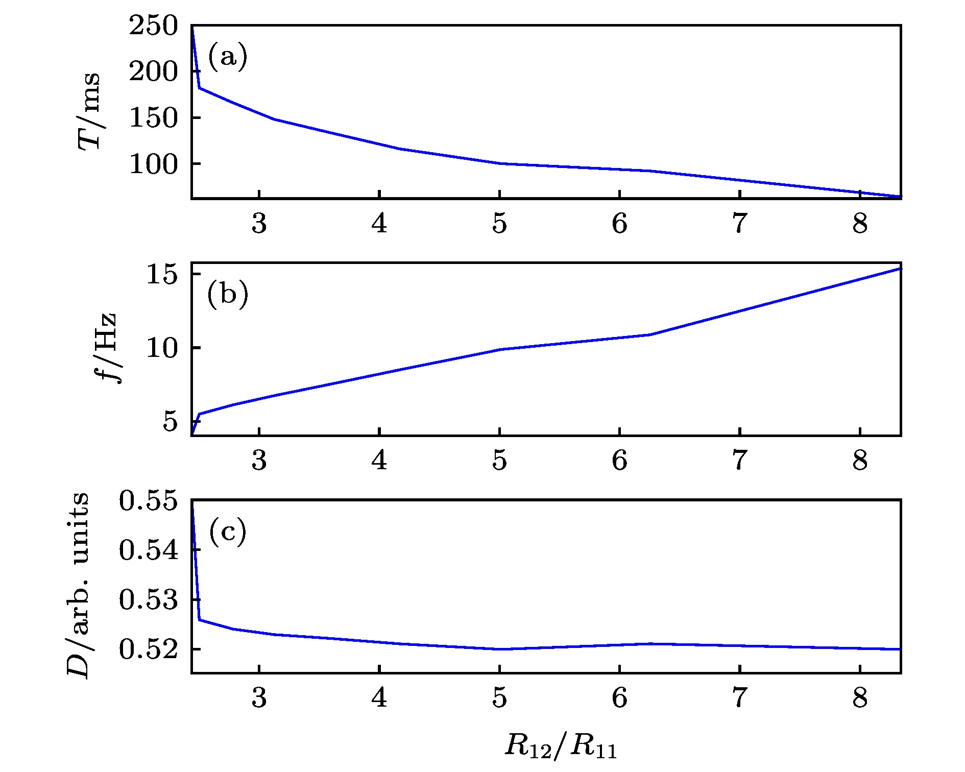
图 10
${R_{12}}/{R_{11}}$ 作为参变量时, 振荡器性能参数随电路参数变化的曲线 (a) T; (b) f; (c) DFig. 10. Curve of Oscillator Performance Parameters with Circuit parameter changes (
${R_{12}}/{R_{11}}$ as a parameter variable): (a) T; (b) f; (c) D.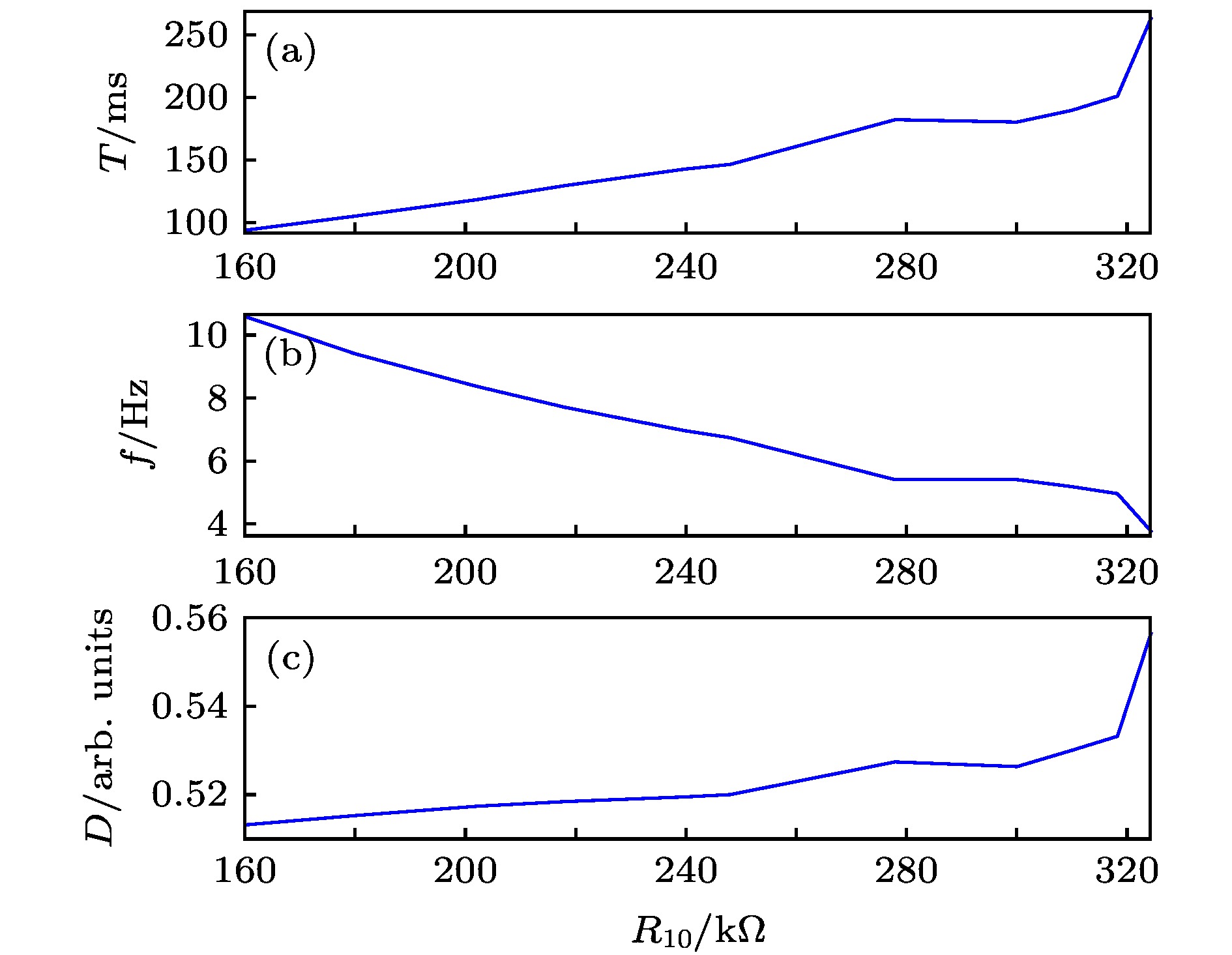
图 11
${R_{10}}$ 作为参变量时, 振荡器性能参数随电路参数变化的曲线 (a) T; (b) f; (c) DFig. 11. Curve of oscillator performance parameters with circuit parameter changes (
${R_{10}}$ as a parameter variable): (a) T; (b) f; (c) D.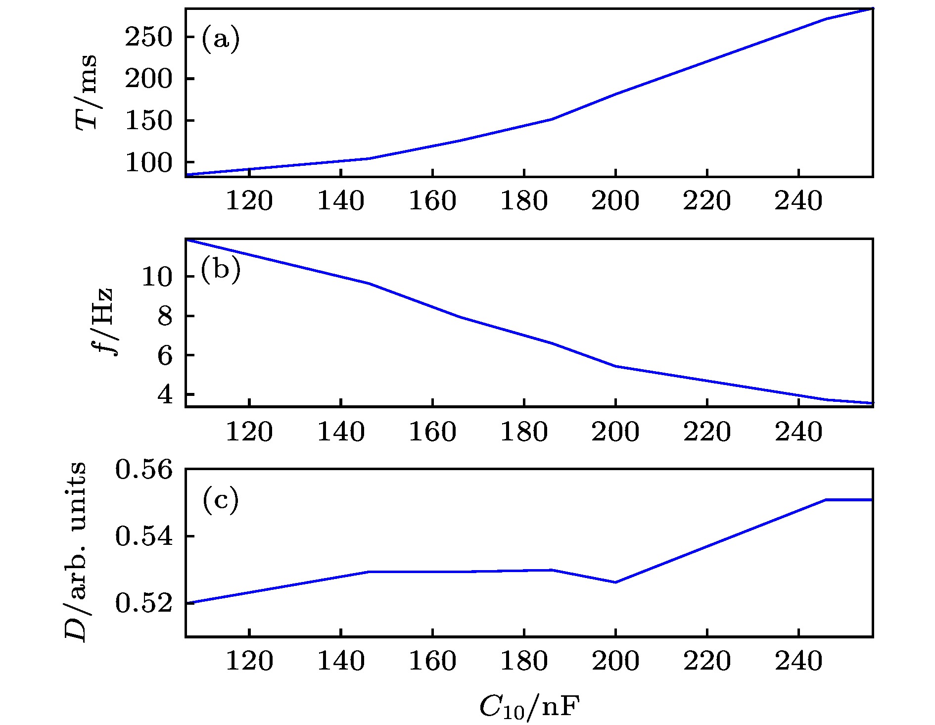
图 12
${C_2}$ 作为参变量时, 振荡器性能参数随电路参数变化的曲线 (a) T; (b) f; (c) DFig. 12. Curve of Oscillator Performance Parameters with Circuit parameter changes (
${C_2}$ as a parameter variable): (a) T; (b) f; (c) D.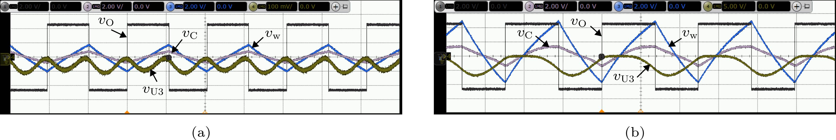
图 13 忆容器振荡器硬件电路实验振荡波形(图(a)和(b)中
${v_{\rm{O}}}$ 、${v_C}$ 和${v_w}$ 的纵轴均为2 V/格) (a)${R_{12}}/{R_{11}} = 5$ , 其中${v_{{\rm{U}}3}}$ 纵轴为100 mV/格, 时间轴为50 ms/格; (b)${R_{12}}/{R_{11}} = 2.427$ , 其中${v_{{\rm{U}}3}}$ 纵轴为5 V/格, 时间轴为100 ms/格Fig. 13. Experimental oscillation waveforms of memcapacitor multivibrator: (a)
${R_{12}}/{R_{11}} = 5$ ; (b)${R_{12}}/{R_{11}} = 2.427$ . The vertical axes of${v_{\rm{O}}}$ 、${v_C}$ and${v_w}$ in Fig(a) and Fig (b) are both 2 V/lattice. The vertical and horizontal axes of${v_{{\rm{U}}3}}$ in Fig(a) are 100 mV/lattice and 50 ms/lattice, respectively. The vertical and horizontal axes of${v_{{\rm{U}}3}}$ in Fig(b) are 5 V/lattice and 100 ms/lattice, respectively.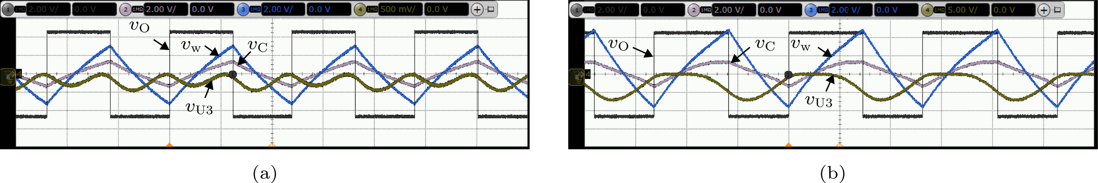
图 14 忆容振荡器硬件电路实验振荡波形(图中
${v_{\rm{O}}}$ 、${v_C}$ 和${v_w}$ 纵轴均为2 V/格, 图(a)中${v_{{\rm{U}}3}}$ 纵轴为500 mV/格, 时间轴为50 ms/格, 图(b)中${v_{{\rm{U}}3}}$ 纵轴为5 V/格, 时间轴为100 ms/格) (a)${R_{10}} = 202\;{\rm{k}}\Omega$ ; (b)${R_{10}} = 324\;{\rm{k}}\Omega$ Fig. 14. Experimental oscillation waveforms of memcapacitor multivibrator: (a)
${R_{10}} = 202\;{\rm{k}}\Omega$ ; (b)${R_{10}} = 324\;{\rm{k}}\Omega$ . The vertical axis of${v_{\rm{O}}}$ 、${v_C}$ and${v_w}$ in Fig. (a) and Fig. (b) are both 2 V/lattice. The vertical and horizontal axes of${v_{{\rm{U}}3}}$ in Fig. (a) are 500 mV/lattice and 50 ms/lattice, respectively. The vertical and horizontal axes of${v_{{\rm{U}}3}}$ in Fig. (b) are 5 V/lattice and 100 ms/lattice, respectively.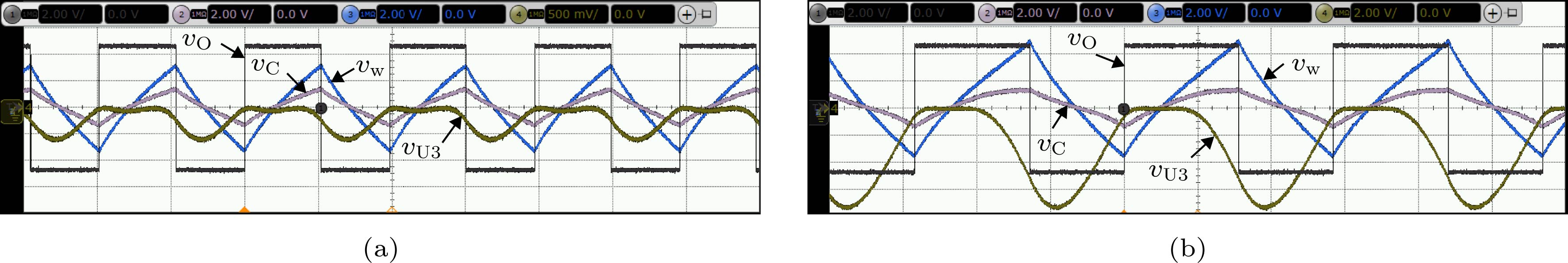
图 15 忆容振荡器硬件电路实验振荡波形(图中
${v_{\rm{O}}}$ 、${v_C}$ 和${v_w}$ 纵轴均为2 V/格, 图(a)中${v_{{\rm{U3}}}}$ 纵轴为500 mV/格, 时间轴为50 ms/格, 图(b)中${v_{{\rm{U3}}}}$ 纵轴为2 V/格, 时间轴为100 ms/格) (a) C2 = 146 nF; (b) C2 = 256 nFFig. 15. Experimental oscillation waveforms of memcapacitor multivibrator: (a) C2 = 146 nF; (b) C2 = 256 nF. The vertical axes of
${v_{\rm{O}}}$ 、${v_C}$ and${v_w}$ in Fig. (a) and Fig. (b) are both 2 V/lattice. The vertical and horizontal axes of${v_{{\rm{U}}3}}$ in Fig. (a) are 500 mV/lattice and 50 ms/lattice, respectively. The vertical and horizontal axes of${v_{{\rm{U}}3}}$ in Fig. (b) are 2 V/lattice and 100 ms/lattice, respectively.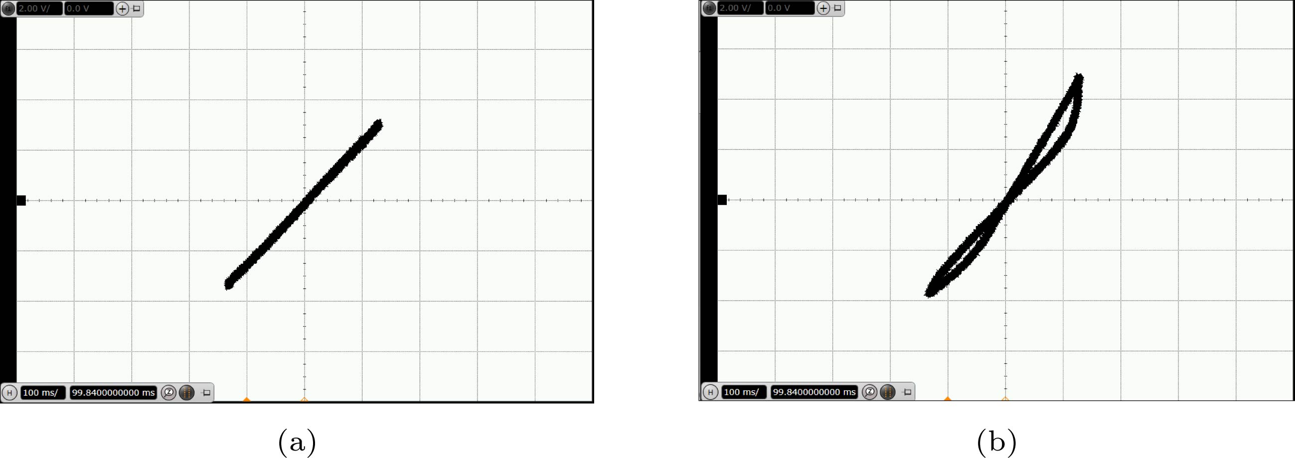
图 16
${R_{10}}$ 为不同值时振荡电路中忆容器的滞回曲线(横坐标和纵坐标分别对应于${v_{AB}}$ 和${v_w}$ ) (a)${R_{10}} = 202\;{\rm{k}}\Omega$ ; (b)${R_{10}} = 324\;{\rm{k}}\Omega$ Fig. 16. The pinched hysteresis loops of memcapacitor with different values of R10 in oscillating circuit: (a)
${R_{10}} = 202\;{\rm{k}}\Omega$ ; (b)${R_{10}} = 324\;{\rm{k}}\Omega$ . The horizontal and vertical axes correspond to${v_{AB}}$ and${v_w}$ , respectively. -
[1] Di Ventra M, Pershin Y V, Chua L O 2009 Proc. IEEE 97 1717
Google Scholar
[2] Wang G Y, Cai B Z, Jin P P, Hu T L 2017 Chin. Phys. B 25 010503
[3] Pershin Y V, Di Ventra M 2012 Proc. IEEE 100 2071
Google Scholar
[4] Driscoll T, Quinn J, Klein S, Kim H T, Kim B J 2010 Appl. Phys. Lett. 97 093502
Google Scholar
[5] Li Y F, Yang C Y, Yu Y B 2017 Proceedings of the 36th Chinese Control Conference Dalian, China, July 26−28, 2017 p5110
[6] Flak J, Lehtonen E, Laiho M, Rantala A, Prunnila M, Haatainen T 2014 Semicond. Sci. Technol. 29 104012
Google Scholar
[7] Noh Y J, Baek Y J, Hu Q, Kang C J, Choi Y J, Lee H H 2015 IEEE Trans. Nanotechnol. 14 798
Google Scholar
[8] Yuan F, Wang G Y, Shen Y R, Wang X Y 2016 Nonlinear Dyn. 86 37
Google Scholar
[9] Fouda M E, Khatib M A, Radwan A G 2013 25th International Conference on Microelectronics Beirut, Lebanon, December 15−18, 2013 p978
[10] Biolek D, Biolek Z, Biolkova V 2010 Electron. Lett. 46 520
Google Scholar
[11] Biolek D, Biolkova V, Kolka Z 2010 IEEE Asia Pacific Conference on Circuits and Systems Kuala, Lumpur, Malaysia, December 6−9, 2010 p800
[12] Yu D S, Liang Y, Chen H 2013 IEEE Trans. Circuits Syst. II, Exp. Briefs 60 207
Google Scholar
[13] Yu D S, Liang Y, Herbert H C I 2014 IEEE Trans. Circuits Syst. II, Exp. Briefs 61 758
Google Scholar
[14] Yu D S, Zhou Z, Herbert H C I 2016 IEEE Trans. Circuits Syst. II, Exp. Briefs 63 1101
Google Scholar
[15] 李志军, 向林波, 肖文润 2017 电子与信息学报 39 1626
Li Z J, Xiang L B, Xiao W R 2017 J. Electron. Inform. Technol. 39 1626
[16] Chua L O 2015 Radioengineering 24 319
Google Scholar
[17] Jin P P, Wang G Y, Herbert H C I 2018 IEEE Trans. Circuits Syst. II, Exp. Briefs 65 246
Google Scholar
[18] Chua L O 2018 Appl. Phys. A-Mater. 124 563
Google Scholar
[19] Yu D S, Herbert H C I 2014 IEEE Trans. Circuits Syst. I, Reg. Papers 61 2888
Google Scholar
[20] Pershin Y V, Massimiliano D V 2011 Electron. Lett. 47 243
Google Scholar

 下载:
下载:


计量
- 文章访问数: 12614
- PDF下载量: 142
- 被引次数: 0
