


-
In the past, the memristor model and its application research have mainly focused on constructing and analyzing the memristor model and its equivalent circuit model based on the basic concept of memristor, while the research based on commercial memristive devices in the market has been rare. According to the theoretical relationship between meminductor and memristor, a new model of meminductor is constructed based on Knowm memristor, the first commercial memristor chip in the world, combined with the second-generation current conveyor and transconductance operational amplifier. By adjusting the frequency and the amplitude of the input voltage and the transconductance gain of the transconductance operational amplifier, the continuous adjustment of the meminductance can be effectively achieved in the circuit. The LTspice circuit model and hardware experimental circuit of the proposed meminductor are designed. The validity of the new meminductor model and the correctness of the design method are verified by LTspice simulations and circuit experiments.
-
Keywords:
- Knowm memristor /
- transconductance /
- meminductor
[1] Chua L O 1971 IEEE Trans. Circuit Theory 18 507
 Google Scholar
[2] Strukov D B, Snider G S, Stewart D R, Williams R S 2008 Nature 453 80
Google Scholar
[3] Jo S H, Chang T, Ebong I, Bhadviya B B, Mazumder P, Lu W 2010 Nano Lett. 10 1297
Google Scholar
[4] Corinto F, Ascoli A, Gilli M 2011 IEEE Trans. Circuits Syst. I 58 1323
Google Scholar
[5] Hu W, Wei R S 2019 IEEE Trans. Electron Devices 66 2589
Google Scholar
[6] Luo S J, Xu N, Guo Z, Zhang Y, Hong H, You L 2019 IEEE Electron Device Lett. 40 635
Google Scholar
[7] Yakopcic C, Taha T M, Subramanyam G, Pino R E, Rogers S 2011 IEEE Electron Device Lett. 32 1436
Google Scholar
[8] Corinto F, Ascoli A 2012 IEEE Trans. Circuits Syst. I 59 2713
Google Scholar
[9] Ventra M D, Pershin Y V, Chua L O 2009 Proc. IEEE 97 1371
Google Scholar
[10] Han J H, Song C, Gao S, Wang Y Y, Chen C, Pan F 2014 ACS Nano 8 10043
Google Scholar
[11] Biolek D, Biolek Z, Biolekova V 2009 Conference on Circuit Theory and Design Antalya, Turkey, August 23−27, 2009 p249
[12] Biolek D, Biolek Z, Biolekova V 2011 Analog Integr. Circuits Sig. Process. 66 129
Google Scholar
[13] Li C, Wang X D 2012 Microelectronics 42 584
[14] 王晓媛, 俞军, 王光义 2018 物理学报 67 098501
Google Scholar
Wang X Y, Yu J, Wang G Y 2018 Acta Phys. Sin. 67 098501
Google Scholar
[15] Wang H, Wang X, Li C D 2013 Abstr. Appl. Anal. DOI:10.1155/2013/281675
[16] Biolek D, Biolek Z, Kolka Z 2010 IEEE Asia Pacific Conference on Circuits and Systems Kuala Lumpur, Malaysia, December 6—9, 2010 p800
[17] Pershin Y V, Ventra M D 2010 Electron. Lett. 46 517
Google Scholar
[18] Pershin Y V, Ventra M D 2011 Electron. Lett. 47 243
Google Scholar
[19] Yu D S, Liang Y, Lu H H C, Fernando T, Hu Y H 2014 Chin. Phys. B 23 070702
Google Scholar
[20] Yu D S, Zhou Z, Iu H H C, Fernando T, Hu Y H 2014 IEEE Trans. Circuits Syst. II 61 758
Google Scholar
[21] Sah M P, Budhathoki R K, Yang C J, Kim H 2014 Circuits Syst. Signal Process. 33 2363
Google Scholar
[22] Wang G Y, Jin P P, Wang X W, Shen Y R, Yuan F, Wang X Y 2016 Chin. Phys. B 25 090502
Google Scholar
[23] 李志军, 曾以成, 谭志平 2014 物理学报 63 098501
Google Scholar
Li Z J, Zeng Y C, Tan Z P 2014 Acta Phys. Sin. 63 098501
Google Scholar
[24] Yunus B 2018 Electrica 18 36
[25] Zhao Q, Wang C H, Zhang X 2019 Chaos 29 013141
Google Scholar
[26] Michael A N, Timothy W M 2014 Plos One 9 e85175
Google Scholar
-

图 4 不同参数情况下的
$\varphi - i$ 关系图 (a)$f$ = 100—140 Hz,${g_{\rm{m}}}$ = 1.62 mA/V; (b)$f$ = 240—400 Hz,${g_{\rm{m}}}$ = 1.62 mA/V; (c)$f$ = 500—1400 Hz,${g_{\rm{m}}}$ = 1.62 mA/V; (d)$f$ = 120 Hz,${g_{\rm{m}}}$ = 1.49—1.97 mA/VFig. 4.
$\varphi - i$ relationship diagram under different parameters: (a)$f$ = 100—140 Hz,${g_{\rm{m}}}$ = 1.62 mA/V; 11. (b)$f$ = 240—400 Hz,${g_{\rm{m}}}$ = 1.62 mA/V; (c)$f$ = 500—1400 Hz,${g_{\rm{m}}}$ = 1.62 mA/V; (d)$f$ = 120 Hz,${g_{\rm{m}}}$ =1.49—1.97 mA/V.
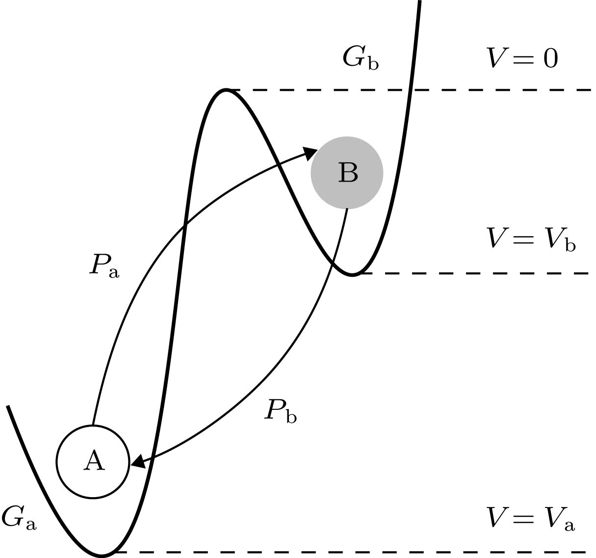
图 5 不同Knowm忆阻器参数情况下的
$\varphi - i$ 关系图 (a)${V_a}$ ,${V_{\rm{b}}}$ ; (b)${G_{\rm{a}}}$ ,${G_{\rm{b}}}$ Fig. 5.
$\varphi - i$ relationship diagram under different Knowm memristor parameters: (a)${V_a}$ ,${V_{\rm{b}}}$ ; (b)${G_{\rm{a}}}$ ,${G_{\rm{b}}}$ .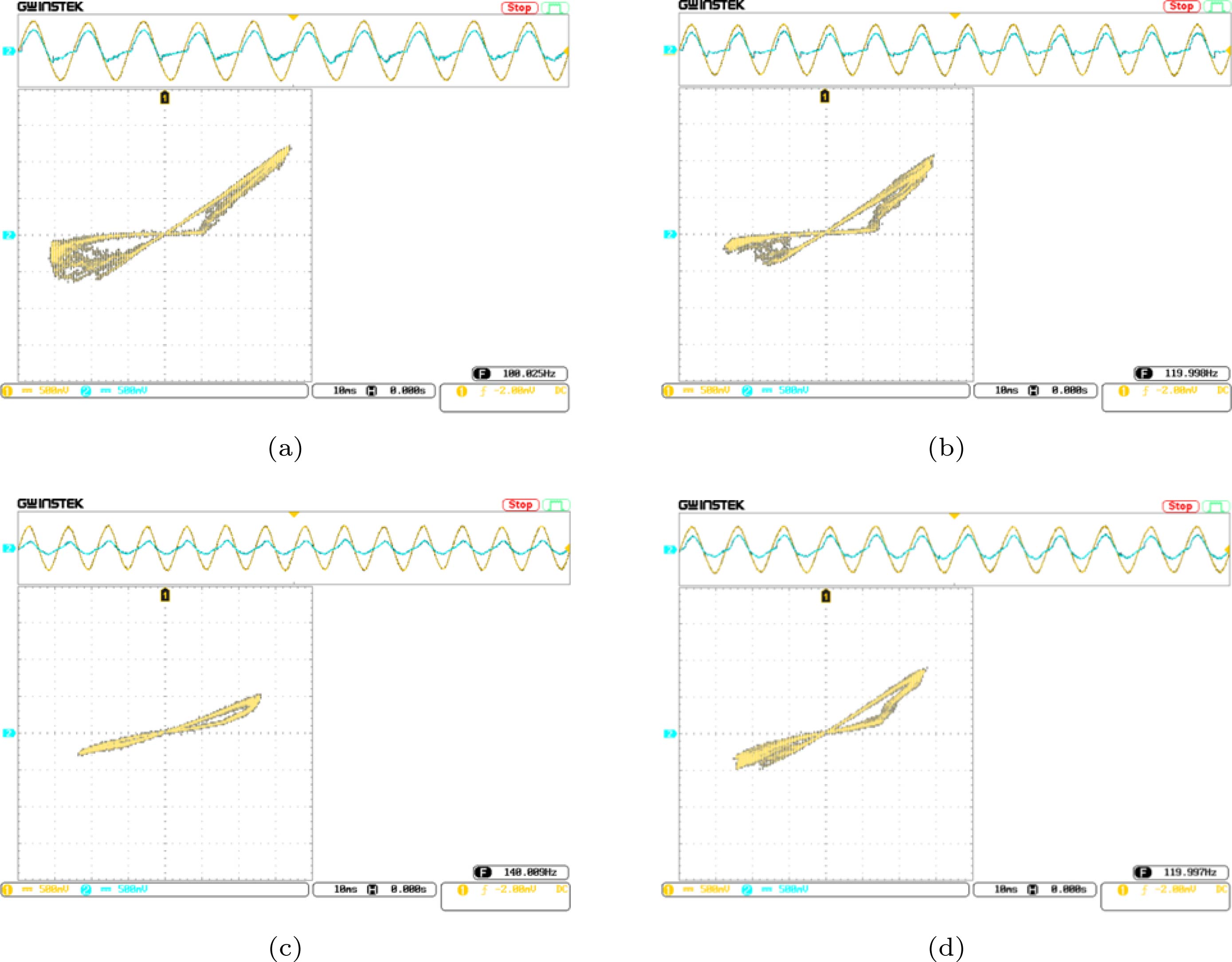
图 7 不同参数作用下的
$\varphi - i$ 关系图, 其中第一通道为${v_{\rm{o}}}(t)/{\rm{V}}$ , 第二通道为${v_{\rm{1}}}(t)/{\rm{V}}$ (a)$f$ = 100 Hz,${g_{\rm{m}}}$ = 1.62 mA/V; (b)$f$ = 120 Hz,${g_{\rm{m}}}$ = 1.62 mA/V; (c)$f$ = 140 Hz,${g_{\rm{m}}}$ = 1.62 mA/V; (d)$f$ = 120 Hz,${g_{\rm{m}}}$ = 1.49 mA/VFig. 7.
$\varphi - i$ relationship diagram under different parameters. The first channel is${v_{\rm{o}}}(t)/{\rm{V}}$ , and the second channel is$ {v_{{1}}}(t)/{\rm{V}} $ : (a)$f$ = 100 Hz,${g_{\rm{m}}}$ = 1.62 mA/V; (b)$f$ = 120 Hz,${g_{\rm{m}}}$ = 1.62 mA/V; (c)$f$ = 140 Hz,${g_{\rm{m}}}$ = 1.62 mA/V; (d)$f$ = 120 Hz,${g_{\rm{m}}}$ = 1.49 mA/V.表 1 LTspice仿真电路中使用的元件参数值
Table 1. Component parameter values used in LTspice simulation circuits.
元件 参数值 ${V_{{\rm{dd}}}}$/V $ \pm {\rm{10 }}$ ${V_{\rm{m}}}$/mV 60 ${R_{\rm{1}}}$/kΩ 56 ${R_2}$/kΩ 56 ${R_6}$/kΩ 51 ${R_7}$/kΩ 200 $C$ $100\;{\rm{ nF}}-{R_3} = {R_4} = 43\;{\rm{k}}\Omega,{R_5} = 22\;{\rm{k}}\Omega $ ${\rm{47\;nF}}-{R_3} = {R_4}={\rm{80\;k}}\Omega,{R_5}={\rm{40\;k}}\Omega $ $10\;{\rm{ nF}}-{R_3} = {R_4} = 100\;{\rm{ k}}\Omega,{R_5} = 50\;{\rm{ k}}\Omega $  下载: 导出CSV
-
[1] Chua L O 1971 IEEE Trans. Circuit Theory 18 507
Google Scholar
[2] Strukov D B, Snider G S, Stewart D R, Williams R S 2008 Nature 453 80
Google Scholar
[3] Jo S H, Chang T, Ebong I, Bhadviya B B, Mazumder P, Lu W 2010 Nano Lett. 10 1297
Google Scholar
[4] Corinto F, Ascoli A, Gilli M 2011 IEEE Trans. Circuits Syst. I 58 1323
Google Scholar
[5] Hu W, Wei R S 2019 IEEE Trans. Electron Devices 66 2589
Google Scholar
[6] Luo S J, Xu N, Guo Z, Zhang Y, Hong H, You L 2019 IEEE Electron Device Lett. 40 635
Google Scholar
[7] Yakopcic C, Taha T M, Subramanyam G, Pino R E, Rogers S 2011 IEEE Electron Device Lett. 32 1436
Google Scholar
[8] Corinto F, Ascoli A 2012 IEEE Trans. Circuits Syst. I 59 2713
Google Scholar
[9] Ventra M D, Pershin Y V, Chua L O 2009 Proc. IEEE 97 1371
Google Scholar
[10] Han J H, Song C, Gao S, Wang Y Y, Chen C, Pan F 2014 ACS Nano 8 10043
Google Scholar
[11] Biolek D, Biolek Z, Biolekova V 2009 Conference on Circuit Theory and Design Antalya, Turkey, August 23−27, 2009 p249
[12] Biolek D, Biolek Z, Biolekova V 2011 Analog Integr. Circuits Sig. Process. 66 129
Google Scholar
[13] Li C, Wang X D 2012 Microelectronics 42 584
[14] 王晓媛, 俞军, 王光义 2018 物理学报 67 098501
Google Scholar
Wang X Y, Yu J, Wang G Y 2018 Acta Phys. Sin. 67 098501
Google Scholar
[15] Wang H, Wang X, Li C D 2013 Abstr. Appl. Anal. DOI:10.1155/2013/281675
[16] Biolek D, Biolek Z, Kolka Z 2010 IEEE Asia Pacific Conference on Circuits and Systems Kuala Lumpur, Malaysia, December 6—9, 2010 p800
[17] Pershin Y V, Ventra M D 2010 Electron. Lett. 46 517
Google Scholar
[18] Pershin Y V, Ventra M D 2011 Electron. Lett. 47 243
Google Scholar
[19] Yu D S, Liang Y, Lu H H C, Fernando T, Hu Y H 2014 Chin. Phys. B 23 070702
Google Scholar
[20] Yu D S, Zhou Z, Iu H H C, Fernando T, Hu Y H 2014 IEEE Trans. Circuits Syst. II 61 758
Google Scholar
[21] Sah M P, Budhathoki R K, Yang C J, Kim H 2014 Circuits Syst. Signal Process. 33 2363
Google Scholar
[22] Wang G Y, Jin P P, Wang X W, Shen Y R, Yuan F, Wang X Y 2016 Chin. Phys. B 25 090502
Google Scholar
[23] 李志军, 曾以成, 谭志平 2014 物理学报 63 098501
Google Scholar
Li Z J, Zeng Y C, Tan Z P 2014 Acta Phys. Sin. 63 098501
Google Scholar
[24] Yunus B 2018 Electrica 18 36
[25] Zhao Q, Wang C H, Zhang X 2019 Chaos 29 013141
Google Scholar
[26] Michael A N, Timothy W M 2014 Plos One 9 e85175
Google Scholar


 下载:
下载:


计量
- 文章访问数: 11589
- PDF下载量: 195
- 被引次数: 0
