


-
为解决高重复频率大能量激光放大器的热管理问题, 采用数值模拟与实验分析的方法, 对背面水冷Nd:YAG激活镜放大器的流体散热进行了研究. 基于低雷诺数k-ε湍流模型, 建立了流-固共轭传热多物理场耦合分析模型, 对比分析了近壁面处理方法对流体流动、对流扩散和热传导过程及温度分布的影响, 分析研究了不同冷却液流量和泵浦参数对流场特性、激光介质温度和波前分布的影响. 数值模拟表明: 激光介质的温度分布与固液边界层内的黏性作用密切相关, 且冷却液的热扩散主要发生在100 μm范围内; 激光介质的热沉积分布中心对称, 而温度分布沿水流方向不对称, 最大温升位于出水口端且基本保持不变; 增益介质前表面的温度分布与介质的波前分布随冷却液流量非线性变化, 而随泵浦参数线性变化; 实验结果与数值模拟符合较好.In order to deal with the thermal management problem of high-energy high-repetition rate laser amplifiers, the efficient heat removal in water-cooled Nd:YAG active mirror amplifiers is investigated in detail through numerical modeling and experimental analysis. According to the low Reynolds number k-ε turbulence model, a full fluid-solid conjugate heat transfer model is established to give a comprehensive model of flow and thermal characteristics in three dimensions. The thermal distributions obtained from the model are then used to calculate all mechanical stresses in the laser medium and thermally-induced wavefront distortions. In comparison with the standard k-ε turbulence model, the influences of the near-wall treatments of the above model on the process of fluid flow, convection diffusion and heat conduction, and temperature distributions are analyzed. Meanwhile, the effects of coolant flow rate and pump parameter on the flow field characteristics, temperature and wavefront distributions of the YAG disk are also studied. Numerical simulation results reveal that the temperature distribution of the laser medium is closely related to the viscous effect in the solid-liquid boundary layer. Although the heat deposition distribution of the laser medium is symmetrical, the temperature profile is asymmetrical as a result of the increasing water temperature along the water flow. The maximum temperature rise of the disk is at the outlet end, and the position remains almost unchanged. The front-surface temperature distributions and wavefront profiles of Nd:YAG vary nonlinearly with the coolant flow rates, but linearly with the pump parameter. Model predictions show that when the laser amplifier operates at a repetition rate of 50 Hz, the thermal diffusion of the coolant mainly occurs in a range of 100 μm, and the maximum temperature difference of the coolant reaches up to 10.85 ℃. Correspondingly, the maximum temperature variation over the front-surface active region is less than 4 ℃, with an average temperature of 49.62 ℃, which leads to a total peak-to-valley wave front distortion of 7.27λ. The experimentally measured temperature distributions are in reasonable agreement with numerical simulations. The research results are beneficial to designing and optimizing the high-energy, high-repetition rate water-cooled Nd:YAG active mirror amplifiers.
-
Keywords:
- active mirror amplifier /
- low Reynolds number k-ε model /
- fluid-solid conjugate heat transfer /
- temperature distribution
[1] Chanteloup J C, Albach D 2011 IEEE Photonics J. 3 245
 Google Scholar
[2] Erlandson A C, Aceves S M, Bayramian A J, Bullington A L, Beach R J 2011 Opt. Mater. Express 1 1341
Google Scholar
[3] Zheng J G, Jiang X Y, Yan X W, Zhang J, Wang Z G 2014 High Power Laser Sci. 2 1
Google Scholar
[4] Liu J, Li L, Shi X C, Chen R F, Wang J L, Chen W B 2018 Chin. Opt. Lett. 16 121402
Google Scholar
[5] Bayramian A, Armstrong P, Ault E, Beach R, Bibeau C, Caird J 2007 Fusion Sci. Technol. 52 383
Google Scholar
[6] Mason P, Divoky M, Ertel K, Pilar J, Butcher T, Hanus M 2017 Optica 4 438
Google Scholar
[7] Goncalves T, Albach D, Vincent B, Arzakantsyan M, Chanteloup J C 2013 Opt. Express 21 855
Google Scholar
[8] Liu T, Sui Z, Chen L, Li Z, Liu Q, Gong M, Fu X 2017 Opt. Express 25 21981
Google Scholar
[9] Jiang X, Wang Z, Yan X, Xue Q, Dai W, Wu W, Yao K 2019 Proc. SPIE 11333 113330M
Google Scholar
[10] Vanda J, Muresan M G, Bilek V, Sebek M, Hanus M 2017 Proc. SPIE 10447 104471A
Google Scholar
[11] Rostohar D, Koerner J, Boedefeld R, Lucianetti A, Mocek T 2017 IEEE 3rd International Forum on Research and Technologies for Society and Industry (RTSI) Modena, Italy, September 11–13, 2017 p17256709
[12] Sawicka M, Divoky M, Slezak O, Vido M D, Lucianetti A, Mocek T 2019 IEEE J. Quantum Electron. 55 1
Google Scholar
[13] Chi H, Baumgarten C M, Jankowska E, Dehne K A, Murray G, Meadows A R, Berrill M, Reagan B A, Rocca J J 2019 J. Opt. Soc. Am. B 36 1084
Google Scholar
[14] Cini L, Mackenzie J I 2017 Appl. Phys. B 123 273
Google Scholar
[15] Dindarlu M H, Tehrani M K, Saghafifar H, Maleki A 2016 Laser Phys. 26 055001
Google Scholar
[16] 黄文发, 李学春, 王江峰, 卢兴华, 张玉奇, 范薇, 林尊琪 2015 物理学报 64 087801
Google Scholar
Huang W F, Li X C, Wang J F, Lu X H, Zhang Y Q, Fan W, Lin Z Q 2015 Acta Phys. Sin. 64 087801
Google Scholar
[17] Shen Y, Bo Y, Zong N, Guo Y D, Peng Q J, Li J, Pan Y B, Zhang J Y, Cui D F, Xu Z Y 2015 IEEE J. Sel. Top. Quantum Electron. 21 1602408
Google Scholar
[18] 李策, 冯国英, 杨火木 2016 物理学报 65 054204
Google Scholar
Li C, Feng G Y, Yang H M 2016 Acta Phys. Sin. 65 054204
Google Scholar
[19] Mason P D, Fitton M, Lintern A, Banerjee S, Ertel K 2015 Appl. Opt. 54 4227
Google Scholar
[20] Li P L, Fu X, Liu Q, Gong M L 2013 J. Opt. Soc. Am. B 30 2161
Google Scholar
[21] Wang J R, Min J C, Song Y Z 2006 Appl. Therm. Eng. 26 549
Google Scholar
[22] 杨火木, 冯国英, 魏泳涛, 母健, 王树同, 王绍朋, 唐淳, 周寿桓 2013 中国激光 40 0902004
Google Scholar
Yang H M, Feng G Y, Wei Y T, Mu J, Wang S T, Wang S P, Tang C, Zhou S H 2013 Chin. J. Las. 40 0902004
Google Scholar
[23] 王福军 2004 计算流体动力学分析: CFD软件原理与应用 (北京: 清华大学出版社) 第126—131页
Wang F J 2004 Computational Fluid Dynamics Analysis: Principle and Application of CFD Software (Beijing: Tsinghua University Press) pp126—131 (in Chinese)
[24] Fan T Y 1993 IEEE J. Quantum Electron. 29 1457
Google Scholar
[25] 严雄伟, 於海武, 曹丁象, 李明中, 蒋东镔 2009 物理学报 58 4230
Google Scholar
Yan X W, Yu H W, Cao D X, Li M Z, Jiang D B 2009 Acta Phys. Sin. 58 4230
Google Scholar
[26] Aggarwal R L, Ripin D J, Ochoa J R, Fan T Y 2005 J. Appl. Phys. 98 103514
Google Scholar
-
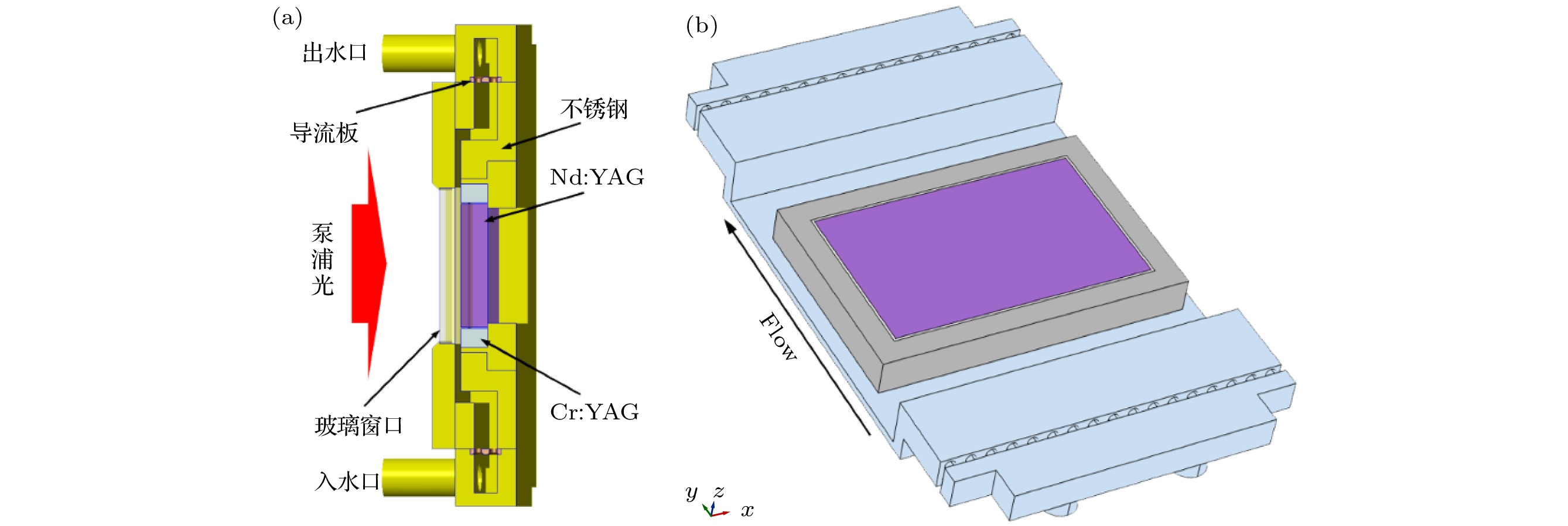
图 1 水冷Nd:YAG激活镜放大器的模型 (a) 激活镜放大器结构; (b) 流道结构
Fig. 1. Simulational model of water-cooled Nd:YAG active mirror amplifeir: (a) Configuration of the active mirror amplifier; (b) configuration of cooling channel.

图 2 (a) 激光介质中横向热沉积分布; (b) 流道中心截面流速分布比较; (c) 标准k-ε模型和(d) 低雷诺数k-ε模型中激光介质及固液边界层中的温度分布
Fig. 2. (a) Transverse heat density distribution in the laser medium. (b) Comparison of flow velocity distribution across the center of the cooling channel. Temperature profiles in the laser medium and the solid and liquid boundary layers obtained by (c) the standard k-ε model and (d) low Re k-ε model.

图 3 激光介质沿 (a) x方向、(b) y方向、(c) z方向的应力分布; (d) 激光介质沿z方向的形变分布
Fig. 3. Thermal stress distributions in the laser medium along (a) x direction, (b) y direction, (c) z direction; (d) z-deformation of the laser medium.

图 4 Nd:YAG中热致波前畸变(λ = 1064 nm) (a) 热光效应引起的畸变; (b) 形变引起的畸变; (c) 总波前畸变
Fig. 4. Thermally induced wavefront distortions in the Nd:YAG slab: (a) Thermal-optical effect induced wavefront distortion; (b) the deformation induced wavefront distortion; (c) the overall wavefront distortion.

图 5 流量对Nd:YAG前表面温度分布和介质波前的影响 (a) 中心截面(x = 0)处温度分布曲线; (b) 平均温度和沿水流温差分布; (c) 波前分布
Fig. 5. Temperature field distributions and wavefront distortions of gain medium at different flow rates: (a) Temperature profiles across the center of gain medium; (b) mean temperature and temperature difference distributions; (c) wavefront distortions.

图 6 Nd:YAG前表面平均温度、温差及介质波前随(a), (c)泵浦功率和(b), (d)重复频率的变化
Fig. 6. Average temperature and temperature difference on the front surface of Nd:YAG and the wavefront distortions of the gain medium at different (a), (c) pump intensities and (b), (d) repetition rates.
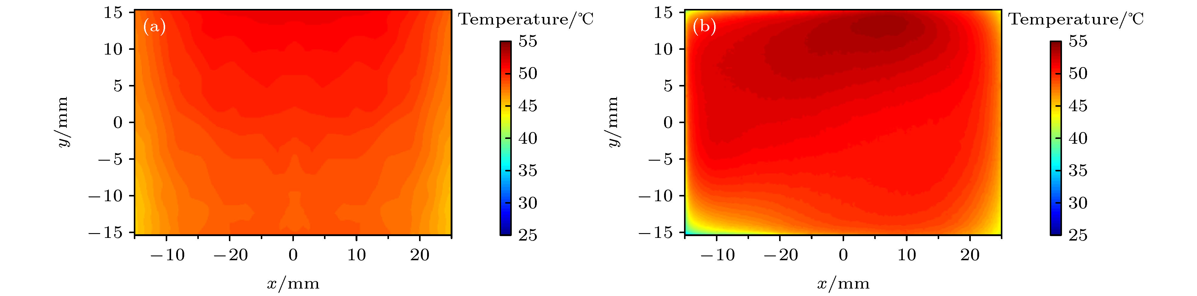
图 7 50 Hz重复频率下Nd:YAG前表面的温度分布 (a) 数值模拟值; (b) 实验测量值
Fig. 7. Temperature field distributions on the front surface of Nd:YAG operating at the repetition rate of 50 Hz: (a) Numerical simulation results; (b) experimental results.

图 8 (a) 实验测量的Nd:YAG最高温度点处沿水流方向的温度分布曲线; (b) Nd:YAG前表面平均温度和温差的理论与实验对比
Fig. 8. (a) Measured longitudinal temperature profiles through the peak temperature of Nd:YAG; (b) theoretical and experimental comparison of the average temperature and temperature difference on the front surface of Nd:YAG.
表 1 计算过程中的物性参数
Table 1. Physical parameters used in the simulation.
物性参数 Nd:YAG Optical adhesive H2O 密度 ρ/(kg·m–3) 4560 1160 997 热导率 k/(W·m–1·K–1) 15.09(T/164.17)–0.75 2.11 × 10⁻³T + 1.81 0.6 比热 Cp/(J·kg–1·K–1) 125.4T 0.4005 – 626.4 1.48 – 9.72 × 10⁻³T + 1.79 × 10⁻⁵T 2 4182 动力黏度 μ/(kg·m–1·s–1) — — 1.0 × 10⁻³ 折射率 n0 1.82 1.65 — 热光系数(dn/dT )/(10–6 K–1) –3.946 + 0.053T – 4.5 × 10⁻⁵T 2 — — 热膨胀系数 α/(10–6 K–1) –1.850 + 0.044T – 5.7 × 10⁻⁵T 2 58 — 杨氏模量 υ/GPa 308 1 — 泊松比 0.232 0.38 —  下载: 导出CSV
-
[1] Chanteloup J C, Albach D 2011 IEEE Photonics J. 3 245
Google Scholar
[2] Erlandson A C, Aceves S M, Bayramian A J, Bullington A L, Beach R J 2011 Opt. Mater. Express 1 1341
Google Scholar
[3] Zheng J G, Jiang X Y, Yan X W, Zhang J, Wang Z G 2014 High Power Laser Sci. 2 1
Google Scholar
[4] Liu J, Li L, Shi X C, Chen R F, Wang J L, Chen W B 2018 Chin. Opt. Lett. 16 121402
Google Scholar
[5] Bayramian A, Armstrong P, Ault E, Beach R, Bibeau C, Caird J 2007 Fusion Sci. Technol. 52 383
Google Scholar
[6] Mason P, Divoky M, Ertel K, Pilar J, Butcher T, Hanus M 2017 Optica 4 438
Google Scholar
[7] Goncalves T, Albach D, Vincent B, Arzakantsyan M, Chanteloup J C 2013 Opt. Express 21 855
Google Scholar
[8] Liu T, Sui Z, Chen L, Li Z, Liu Q, Gong M, Fu X 2017 Opt. Express 25 21981
Google Scholar
[9] Jiang X, Wang Z, Yan X, Xue Q, Dai W, Wu W, Yao K 2019 Proc. SPIE 11333 113330M
Google Scholar
[10] Vanda J, Muresan M G, Bilek V, Sebek M, Hanus M 2017 Proc. SPIE 10447 104471A
Google Scholar
[11] Rostohar D, Koerner J, Boedefeld R, Lucianetti A, Mocek T 2017 IEEE 3rd International Forum on Research and Technologies for Society and Industry (RTSI) Modena, Italy, September 11–13, 2017 p17256709
[12] Sawicka M, Divoky M, Slezak O, Vido M D, Lucianetti A, Mocek T 2019 IEEE J. Quantum Electron. 55 1
Google Scholar
[13] Chi H, Baumgarten C M, Jankowska E, Dehne K A, Murray G, Meadows A R, Berrill M, Reagan B A, Rocca J J 2019 J. Opt. Soc. Am. B 36 1084
Google Scholar
[14] Cini L, Mackenzie J I 2017 Appl. Phys. B 123 273
Google Scholar
[15] Dindarlu M H, Tehrani M K, Saghafifar H, Maleki A 2016 Laser Phys. 26 055001
Google Scholar
[16] 黄文发, 李学春, 王江峰, 卢兴华, 张玉奇, 范薇, 林尊琪 2015 物理学报 64 087801
Google Scholar
Huang W F, Li X C, Wang J F, Lu X H, Zhang Y Q, Fan W, Lin Z Q 2015 Acta Phys. Sin. 64 087801
Google Scholar
[17] Shen Y, Bo Y, Zong N, Guo Y D, Peng Q J, Li J, Pan Y B, Zhang J Y, Cui D F, Xu Z Y 2015 IEEE J. Sel. Top. Quantum Electron. 21 1602408
Google Scholar
[18] 李策, 冯国英, 杨火木 2016 物理学报 65 054204
Google Scholar
Li C, Feng G Y, Yang H M 2016 Acta Phys. Sin. 65 054204
Google Scholar
[19] Mason P D, Fitton M, Lintern A, Banerjee S, Ertel K 2015 Appl. Opt. 54 4227
Google Scholar
[20] Li P L, Fu X, Liu Q, Gong M L 2013 J. Opt. Soc. Am. B 30 2161
Google Scholar
[21] Wang J R, Min J C, Song Y Z 2006 Appl. Therm. Eng. 26 549
Google Scholar
[22] 杨火木, 冯国英, 魏泳涛, 母健, 王树同, 王绍朋, 唐淳, 周寿桓 2013 中国激光 40 0902004
Google Scholar
Yang H M, Feng G Y, Wei Y T, Mu J, Wang S T, Wang S P, Tang C, Zhou S H 2013 Chin. J. Las. 40 0902004
Google Scholar
[23] 王福军 2004 计算流体动力学分析: CFD软件原理与应用 (北京: 清华大学出版社) 第126—131页
Wang F J 2004 Computational Fluid Dynamics Analysis: Principle and Application of CFD Software (Beijing: Tsinghua University Press) pp126—131 (in Chinese)
[24] Fan T Y 1993 IEEE J. Quantum Electron. 29 1457
Google Scholar
[25] 严雄伟, 於海武, 曹丁象, 李明中, 蒋东镔 2009 物理学报 58 4230
Google Scholar
Yan X W, Yu H W, Cao D X, Li M Z, Jiang D B 2009 Acta Phys. Sin. 58 4230
Google Scholar
[26] Aggarwal R L, Ripin D J, Ochoa J R, Fan T Y 2005 J. Appl. Phys. 98 103514
Google Scholar

 下载:
下载:
计量
- 文章访问数: 7459
- PDF下载量: 100
- 被引次数: 0
