


-
Cavity quantum electrodynamic system with strongly coupled single atoms provides a good platform for studying quantum information processing, quantum simulation, quantum network, and distributed quantum computing. Cooling and trapping single atoms is a crucial technique in the quantum technology. At present, in a high-finesse cavity with finite space, cooling and trapping single atoms is a big challenge, even though it is a mature technique for free space. Great efforts have been made to cool and trap single atoms inside a cavity, and for a trapped atom its lifetime has reached as long as tens of seconds. Developing a more flexible method of cooling and trapping single atoms in a cavity is still essential for a strongly coupled cavity quantum electrodynamic system. In this work, we demonstrate experimentally that a single cesium atom in a cavity can be trapped by utilizing a single optical tweezer settled in cavity mode, and its lifetime is (2.60 ± 0.18) s. The experiment is carried out in a Fabry-Perot cavity, which is assembled by two concave mirrors each with a curvature radius of 100 mm, and cavity length of 335 μm. The concave surfaces are highly reflective, and the cavity has a finesse of 6.1 × 10⁴. The 1080 nm optical tweezer with a waist of 2 μm is formed by an achromatic lens group with a numerical aperture of 0.4. At first, the precooled atomic assemble released from the magneto-optical trap (MOT) is transferred into cavity mode by an optical dipole trap with a waist of 36 μm. Then, one of the successfully transferred atoms is captured by the optical tweezer with the aid of cavity cooling mechanism. A blue detuned cavity locking laser is used as a standing-wave optical trap along the cavity axis. The signal of successfully trapped one atom is obtained by recording transmission of the cavity that will decrease owing to the strong coupling induced vacuum Rabi splitting. Finally, we demonstrate the precise manipulation of the atom-cavity coupling strength, which is achieved by scanning the position of the trapped atom step by step by using a high-precision translation stage. The system realized in this work can be used to study the dynamics of single atom-photon interactions with adjustable coupling strength. In addition, the mechanism adopted in this work is compatible with constructing tweezer arrays inside cavity mode, and thus possesses more flexibility and great potentials in cavity-based quantum entanglement and quantum simulation.
-
Keywords:
- cavity quantum electrodynamic /
- single atom /
- dipole trap /
- strong coupling
[1] Ritter S, Nolleke C, Hahn C, Reiserer A, Neuzner A, Uphoff M, Mucke M, Figueroa E, Bochmann J, Rempe G 2012 Nature 484 195
 Google Scholar
[2] Reiserer A, Rempe G 2015 Rev. Mod. Phys. 87 1379
Google Scholar
[3] Yang C P, Chu S I, Han S 2004 Phys. Rev. A 70 022329
Google Scholar
[4] Daiss S, Langenfeld S, Welte S, Distante E, Thomas P, Hartung L, Morin O, Rempe G 2021 Science 371 614
Google Scholar
[5] Hartmann M J 2016 J. Opt. 18 104005
Google Scholar
[6] Kaufman A M, Lester B J, Foss Feig M, Wall M L, Rey A M, Regal C A 2015 Nature 527 208
Google Scholar
[7] Pellizzari T, Gardiner S A, Cirac J I, Zoller P 1995 Phys. Rev. Lett. 75 3788
Google Scholar
[8] Li J F, Wang Y F, Su K Y, Liao K Y, Zhang S C, Yan H, Zhu S L 2019 Chin. Phys. Lett. 36 074202
Google Scholar
[9] Cho J Y, Lee H W 2004 Phys. Rev. A 70 034305
Google Scholar
[10] Strobel H, Muessel W, Linnemann D, Zibold T, Hume D B, Pezze L, Smerzi A, Oberthaler M K 2014 Science 345 424
Google Scholar
[11] 王婧, 何军, 张天才, 王军民 2008 物理 37 103
Wang J, He J, Zhang T C, Wang J M 2008 Physics 37 103
[12] Maunz P, Puppe T, Schuster I, Syassen N, Pinkse P W H, Rempe G 2004 Nature 428 50
Google Scholar
[13] Horak P, Hechenblaikner G, Gheri K M, Stecher H, Ritsch H 1997 Phys. Rev. Lett. 79 4974
Google Scholar
[14] Vuletic V, Chu S 2000 Phys. Rev. Lett. 84 3787
Google Scholar
[15] Chan H W, Black A T, Vuletic V 2003 Phys. Rev. Lett. 90 063003
Google Scholar
[16] Murr K, Nussmann S, Puppe T, Hijlkema M, Weber B, Webster S C, Kuhn A, Rempe G 2006 Phys. Rev. A 73 063415
Google Scholar
[17] Thompson J D, Tiecke T G, Zibrov A S, Vuletic V, Lukin M D 2013 Phys. Rev. Lett. 110 133001
Google Scholar
[18] Lester B J, Kaufman A M, Regal C A 2014 Phys. Rev. A 90 011804
Google Scholar
[19] Lee H J, Adams C S, Kasevich M, Chu S 1996 Phys. Rev. Lett. 76 2658
Google Scholar
[20] Nussmann S, Murr K, Hijlkema M, Weber B, Kuhn A, Rempe G 2005 Nat. Phys. 1 122
Google Scholar
[21] Turchette Q A, Hood C J, Lange W, Mabuchi H, Kimble H J 1995 Phys. Rev. Lett. 75 4710
Google Scholar
[22] Hood C J, Chapman M S, Lynn T W, Kimble H J 1998 Phys. Rev. Lett. 80 4157
Google Scholar
[23] Mabuchi H, Turchette Q A, Chapman M S, Kimble H J 1996 Opt. Lett. 21 1393
Google Scholar
[24] Munstermann P, Fischer T, Maunz P, Pinkse P W H, Rempe G 1999 Phys. Rev. Lett. 82 3791
Google Scholar
[25] Munstermann P, Fischer T, Pinkse P W H, Rempe G 1999 Opt. Commun. 159 63
Google Scholar
[26] Kuhr S, Alt W, Schrader D, Muller M, Gomer V, Meschede D 2001 Science 293 278
Google Scholar
[27] Dotsenko I, Alt W, Khudaverdyan M, Kuhr S, Meschede D, Miroshnychenko Y, Schrader D, Rauschenbeutel A 2005 Phys. Rev. Lett. 95 033002
Google Scholar
[28] Reiserer A, Nolleke C, Ritter S, Rempe G 2013 Phys. Rev. Lett. 110 223003
Google Scholar
[29] Koch M, Sames C, Kubanek A, Apel M, Balbach M, Ourjoumtsev A, Pinkse P W H, Rempe G 2010 Phys. Rev. Lett. 105 173003
Google Scholar
[30] Doherty A C, Lynn T W, Hood C J, Kimble H J 2000 Phys. Rev. A 63 013401
Google Scholar
[31] Ye J, Vernooy D W, Kimble H J 1999 Phys. Rev. Lett. 83 4987
Google Scholar
[32] McKeever J, Buck J R, Boozer A D, Kuzmich A, Nagerl H C, Stamper Kurn D M, Kimble H J 2003 Phys. Rev. Lett. 90 133602
Google Scholar
[33] Madsen K H, Ates S, Lund-Hansen T, Loffler A, Reitzenstein S, Forchel A, Lodahl P 2011 Phys. Rev. Lett. 106 233601
Google Scholar
[34] Cimmarusti A D, Yan Z, Patterson B D, Corcos L P, Orozco L A, Deffner S 2015 Phys. Rev. Lett. 114 233602
Google Scholar
[35] Schlosser N, Reymond G, Grangier P 2002 Phys. Rev. Lett. 89 023005
Google Scholar
[36] Kuppens S J M, Corwin K L, Miller K W, Chupp T E, Wieman C E 2000 Phys. Rev. A 62 013406
Google Scholar
[37] Kampschulte T, Alt W, Brakhane S, Eckstein M, Reimann R, Widera A, Meschede D 2010 Phys. Rev. Lett. 105 153603
Google Scholar
[38] Thompson R J, Rempe G, Kimble H J 1992 Phys. Rev. Lett. 68 1132
Google Scholar
[39] Zhang Z J, Liu Y, Man Z X 2005 Commun. Theor. Phys. 44 847
Google Scholar
[40] Lucke B, Scherer M, Kruse J, Pezze L, Deuretzbacher F, Hyllus P, Topic O, Peise J, Ertmer W, Arlt J, Santos L, Smerzi A, Klempt C 2011 Science 334 773
Google Scholar
[41] 赵旭, 赵兴东, 景辉 2013 物理学报 62 060302
Google Scholar
Zhao X, Zhao X D, Jing H 2013 Acta Phys. Sin. 62 060302
Google Scholar
-
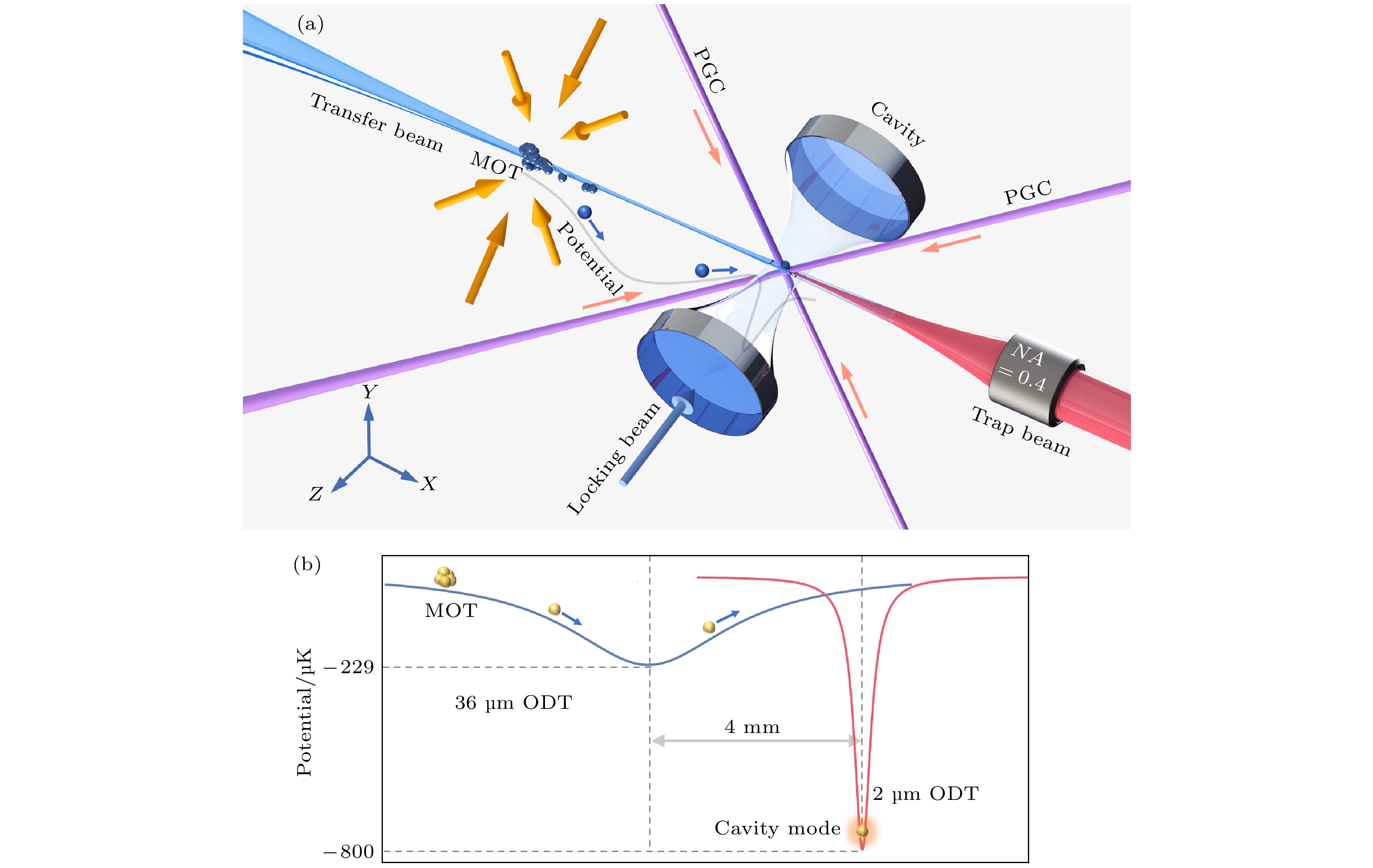
图 1 (a)实验装置示意图. 微光学F-P腔水平放置, 磁光阱(MOT)位于左侧约8 mm处, MOT释放后的铯原子团经光学“传送阱”(蓝色光束, transfer beam)传输至腔模内. 垂直于腔轴的四束对射光(紫色光束, PGC)用于腔内原子冷却, 单个光镊(红色光束, trap beam)用于俘获单个原子. (b)原子传输过程中的光学“传送阱”(36 μm ODT, transfer beam)和光镊(2 μm ODT, trap beam)引起的MOT与腔模之间势能的空间分布, 其阱深分别为–229 μK和–800 μK
Figure 1. (a) Schematic experimental setup. The micro-sized optical F-P cavity is located horizontally, magneto-optical trap (MOT) is about 8 mm to the left. The cesium atoms released from the MOT are transferred into the cavity mode by an optical “conveyor trap” (blue beam, transfer beam) and an optical tweezer (red beam, trap beam) counter-propagating with the belt is used to trap a single atom. Four beams perpendicular to the cavity axis (purple beams, PGC) are for intra-cavity atom cooling. (b) The potential associated with the optical “conveyor trap” (36 μm ODT, transfer beam) and the optical tweezer (2 μm ODT, trap beam) between the MOT and the cavity mode. The corresponding well depths are –229 and –800 μK, respectively.

图 2 (a)腔内单原子信号; (b)腔透射计数分布直方图, 分别展示了空腔透射(蓝色)和俘获单原子后的腔透射(红色)计数分布及相应的泊松分布函数拟合(实线), 取阈值计数40作为鉴别俘获单个原子成功与否的判断标准
Figure 2. (a) Transmission counts of cavity with one atom being trapped. (b) Histogram of cavity transmission counts. Histogram of the empty-cavity transmission (blue) and the cavity with a single atom trapped inside (red). The solid cures are the corresponding fittings by Poisson distribution. Photon count of 40 is taken as threshold to discriminate the trapping of single atom.

图 3 (a)实验时序示意图 (阴影填充部分表示实验中所控制光功率随时序的变化, 坐标轴未按比例绘制); (b)腔内单原子俘获概率随时间的变化 (蓝色圆点表示在t0时刻成功俘获单原子100次, 不同t时刻SPCM计数平均值低于阈值的概率; 蓝色实线为实验数据的e指数拟合, 拟合得到原子寿命为(2.60 ± 0.18) s)
Figure 3. (a) Experimental time sequence (Shaded parts indicate the changes of the optical power in the experiment, and the scale of the time axis is distorted for clarity); (b) the dependence of the survival probability of single atom in the cavity on storage time (The blue dots represent the averaged probability at different storage time t at the case of successfully trapping of one atom at time t0. The probability is obtained with 100 times of experiment trial. The blue solid line indicates data fitting with an exponential function and the fitted lifetime is (2.60 ± 0.18) s).
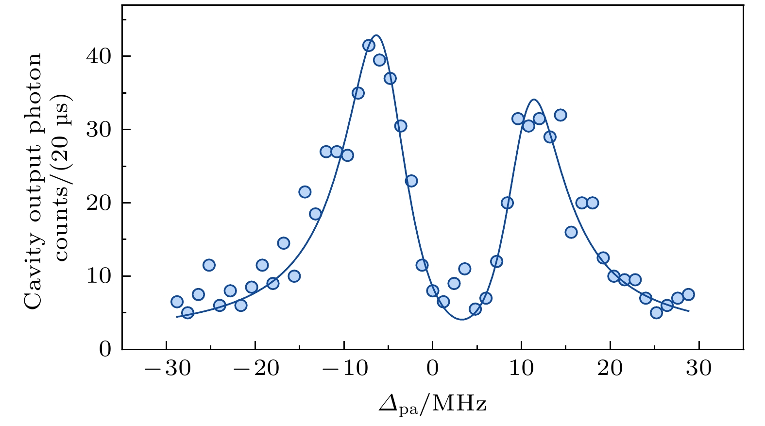
图 4 原子与光学腔耦合最大时的真空拉比分裂谱, 拟合得到其最大的光与原子耦合强度为
${{{g_0}} / {(2}}{\text{π}}) =( 8.10 \pm $ $ 0.16 ){\text{ MHz}}$ Figure 4. Experimental vacuum rabi splitting corresponds to the maximum atom-cavity coupling. The coupling strength between atom and cavity is
${{{g_0}} \mathord{\left/ {\vphantom {{{g_0}} {(2}}} \right. } {(2}}{\text{π)}} = \left( {8.10 \pm 0.16} \right){\text{ MHz}}$ .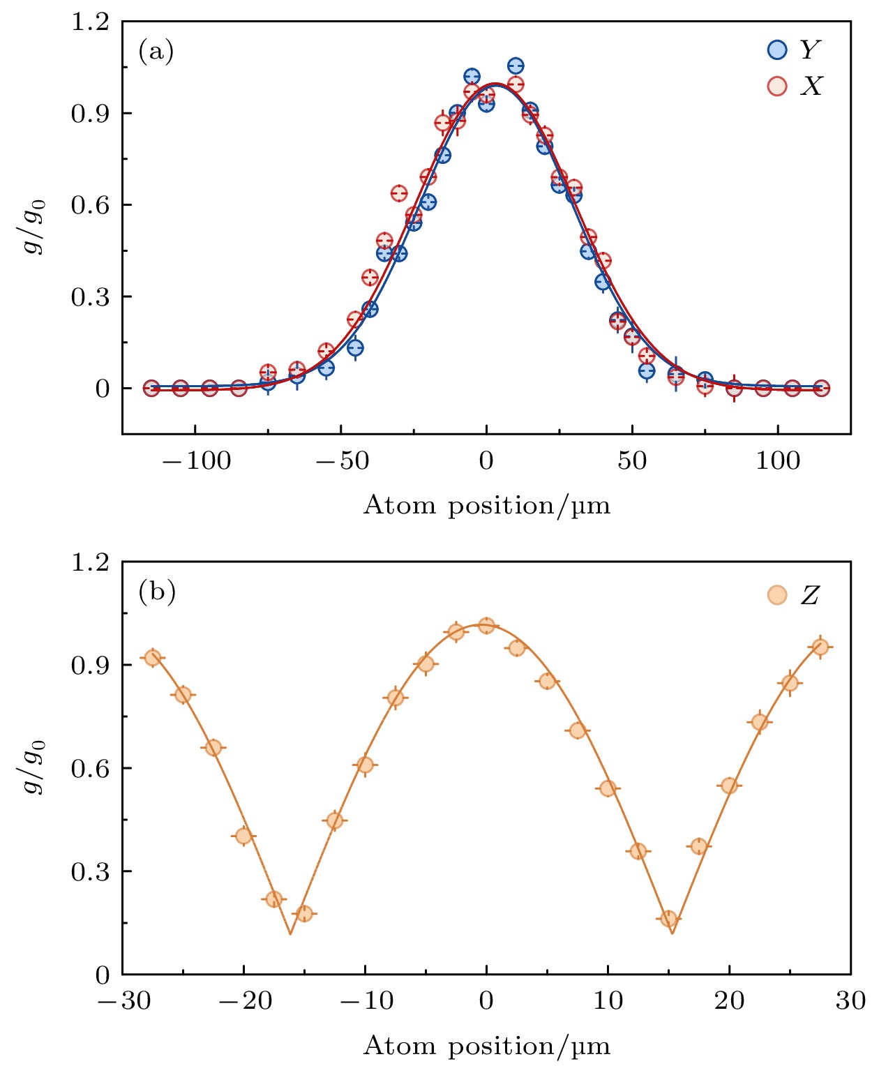
图 5 通过扫描单原子在腔中的位置实现原子与腔耦合强度的精确调节 (a)与腔耦合的单个原子分别沿X (红色圆点)和Y (蓝色圆点)方向扫描时, 耦合强度大小随位置的变化 (红色和蓝色实线分别表示高斯函数拟合的结果); (b)单原子沿Z轴(黄色圆点)方向扫描, 原子处于腔内晶格不同节点时, 耦合强度的大小变化趋势(黄色实线表示与(2)式的预期一致)
Figure 5. Manipulation of the atom-cavity coupling by scanning the position of a single atom in cavity: (a) The position is scanned along X (red circles) and Y (blue circles) axis (Red and blue solid curves are the data fitting by Gaussian functions); (b) position is scanned along cavity axis (Z-axis), the coupling strength with atom trapped on different nodes of the blue trap along Z is in good agreement with the prediction (yellow solid line) of Eq. (2).
-
[1] Ritter S, Nolleke C, Hahn C, Reiserer A, Neuzner A, Uphoff M, Mucke M, Figueroa E, Bochmann J, Rempe G 2012 Nature 484 195
Google Scholar
[2] Reiserer A, Rempe G 2015 Rev. Mod. Phys. 87 1379
Google Scholar
[3] Yang C P, Chu S I, Han S 2004 Phys. Rev. A 70 022329
Google Scholar
[4] Daiss S, Langenfeld S, Welte S, Distante E, Thomas P, Hartung L, Morin O, Rempe G 2021 Science 371 614
Google Scholar
[5] Hartmann M J 2016 J. Opt. 18 104005
Google Scholar
[6] Kaufman A M, Lester B J, Foss Feig M, Wall M L, Rey A M, Regal C A 2015 Nature 527 208
Google Scholar
[7] Pellizzari T, Gardiner S A, Cirac J I, Zoller P 1995 Phys. Rev. Lett. 75 3788
Google Scholar
[8] Li J F, Wang Y F, Su K Y, Liao K Y, Zhang S C, Yan H, Zhu S L 2019 Chin. Phys. Lett. 36 074202
Google Scholar
[9] Cho J Y, Lee H W 2004 Phys. Rev. A 70 034305
Google Scholar
[10] Strobel H, Muessel W, Linnemann D, Zibold T, Hume D B, Pezze L, Smerzi A, Oberthaler M K 2014 Science 345 424
Google Scholar
[11] 王婧, 何军, 张天才, 王军民 2008 物理 37 103
Wang J, He J, Zhang T C, Wang J M 2008 Physics 37 103
[12] Maunz P, Puppe T, Schuster I, Syassen N, Pinkse P W H, Rempe G 2004 Nature 428 50
Google Scholar
[13] Horak P, Hechenblaikner G, Gheri K M, Stecher H, Ritsch H 1997 Phys. Rev. Lett. 79 4974
Google Scholar
[14] Vuletic V, Chu S 2000 Phys. Rev. Lett. 84 3787
Google Scholar
[15] Chan H W, Black A T, Vuletic V 2003 Phys. Rev. Lett. 90 063003
Google Scholar
[16] Murr K, Nussmann S, Puppe T, Hijlkema M, Weber B, Webster S C, Kuhn A, Rempe G 2006 Phys. Rev. A 73 063415
Google Scholar
[17] Thompson J D, Tiecke T G, Zibrov A S, Vuletic V, Lukin M D 2013 Phys. Rev. Lett. 110 133001
Google Scholar
[18] Lester B J, Kaufman A M, Regal C A 2014 Phys. Rev. A 90 011804
Google Scholar
[19] Lee H J, Adams C S, Kasevich M, Chu S 1996 Phys. Rev. Lett. 76 2658
Google Scholar
[20] Nussmann S, Murr K, Hijlkema M, Weber B, Kuhn A, Rempe G 2005 Nat. Phys. 1 122
Google Scholar
[21] Turchette Q A, Hood C J, Lange W, Mabuchi H, Kimble H J 1995 Phys. Rev. Lett. 75 4710
Google Scholar
[22] Hood C J, Chapman M S, Lynn T W, Kimble H J 1998 Phys. Rev. Lett. 80 4157
Google Scholar
[23] Mabuchi H, Turchette Q A, Chapman M S, Kimble H J 1996 Opt. Lett. 21 1393
Google Scholar
[24] Munstermann P, Fischer T, Maunz P, Pinkse P W H, Rempe G 1999 Phys. Rev. Lett. 82 3791
Google Scholar
[25] Munstermann P, Fischer T, Pinkse P W H, Rempe G 1999 Opt. Commun. 159 63
Google Scholar
[26] Kuhr S, Alt W, Schrader D, Muller M, Gomer V, Meschede D 2001 Science 293 278
Google Scholar
[27] Dotsenko I, Alt W, Khudaverdyan M, Kuhr S, Meschede D, Miroshnychenko Y, Schrader D, Rauschenbeutel A 2005 Phys. Rev. Lett. 95 033002
Google Scholar
[28] Reiserer A, Nolleke C, Ritter S, Rempe G 2013 Phys. Rev. Lett. 110 223003
Google Scholar
[29] Koch M, Sames C, Kubanek A, Apel M, Balbach M, Ourjoumtsev A, Pinkse P W H, Rempe G 2010 Phys. Rev. Lett. 105 173003
Google Scholar
[30] Doherty A C, Lynn T W, Hood C J, Kimble H J 2000 Phys. Rev. A 63 013401
Google Scholar
[31] Ye J, Vernooy D W, Kimble H J 1999 Phys. Rev. Lett. 83 4987
Google Scholar
[32] McKeever J, Buck J R, Boozer A D, Kuzmich A, Nagerl H C, Stamper Kurn D M, Kimble H J 2003 Phys. Rev. Lett. 90 133602
Google Scholar
[33] Madsen K H, Ates S, Lund-Hansen T, Loffler A, Reitzenstein S, Forchel A, Lodahl P 2011 Phys. Rev. Lett. 106 233601
Google Scholar
[34] Cimmarusti A D, Yan Z, Patterson B D, Corcos L P, Orozco L A, Deffner S 2015 Phys. Rev. Lett. 114 233602
Google Scholar
[35] Schlosser N, Reymond G, Grangier P 2002 Phys. Rev. Lett. 89 023005
Google Scholar
[36] Kuppens S J M, Corwin K L, Miller K W, Chupp T E, Wieman C E 2000 Phys. Rev. A 62 013406
Google Scholar
[37] Kampschulte T, Alt W, Brakhane S, Eckstein M, Reimann R, Widera A, Meschede D 2010 Phys. Rev. Lett. 105 153603
Google Scholar
[38] Thompson R J, Rempe G, Kimble H J 1992 Phys. Rev. Lett. 68 1132
Google Scholar
[39] Zhang Z J, Liu Y, Man Z X 2005 Commun. Theor. Phys. 44 847
Google Scholar
[40] Lucke B, Scherer M, Kruse J, Pezze L, Deuretzbacher F, Hyllus P, Topic O, Peise J, Ertmer W, Arlt J, Santos L, Smerzi A, Klempt C 2011 Science 334 773
Google Scholar
[41] 赵旭, 赵兴东, 景辉 2013 物理学报 62 060302
Google Scholar
Zhao X, Zhao X D, Jing H 2013 Acta Phys. Sin. 62 060302
Google Scholar

 DownLoad:


Catalog
Metrics
- Abstract views: 5895
- PDF Downloads: 122
- Cited By: 0
