Processing math: 0%

Search

Article

x

留言板

尊敬的读者、作者、审稿人, 关于本刊的投稿、审稿、编辑和出版的任何问题, 您可以本页添加留言。我们将尽快给您答复。谢谢您的支持!

姓名
邮箱
手机号码
标题
留言内容
验证码

Orbital angular momentum mode femtosecond fiber laser with over 100 MHz repetition rate

Wu Hang Chen Liao Li Shuai Du Yu-Fan Zhang Chi Zhang Xin-Liang

Wang Juan-Fen, Wei Xin, Liu Shuai, Yang Ling-Zhen, Xue Ping-Ping, Fan Lin-Lin. Transmission and control of band gap vortex solitons in fractional-order diffraction honeycomb lattices. Acta Phys. Sin., 2024, 73(9): 094205. doi: 10.7498/aps.73.20232005
Citation: Wang Juan-Fen, Wei Xin, Liu Shuai, Yang Ling-Zhen, Xue Ping-Ping, Fan Lin-Lin. Transmission and control of band gap vortex solitons in fractional-order diffraction honeycomb lattices. Acta Phys. Sin., 2024, 73(9): 094205. doi: 10.7498/aps.73.20232005

Orbital angular momentum mode femtosecond fiber laser with over 100 MHz repetition rate

Wu Hang, Chen Liao, Li Shuai, Du Yu-Fan, Zhang Chi, Zhang Xin-Liang
Article Text (iFLYTEK Translation)
PDF
HTML
Get Citation
  • Orbital angular momentum (OAM) lasers have potential applications in large capacity communication systems, laser processing, particle manipulation and quantum optics. OAM mode femtosecond fiber laser has become the research focus due to the advantages of simple structure, low cost and high peak power. At present, OAM mode femtosecond fiber lasers have made some breakthroughs in key parameters such as repetition frequency, pulse width, spectrum width, but it is difficult to achieve good overall performance. Besides, the repetition rate is tens of MHz at present. In this paper, a large-bandwidth mode coupler is made based on the mode phase matching principle. In coupler, the first order mode coupler with 3 dB polarization dependent loss is made by the technology of strong fused biconical taper, and the second order mode coupler with 0.3 dB polarization dependent loss is made by the technology of weak fused biconical taper. By combining the nonlinear polarization rotation mode-locking mechanism, OAM mode femtosecond fiber laser with over 100 MHz repetition rate is built. The achievement of the key parameters is attributed to the selection of dispersion shifted fibers that can accurately adjust intracavity dispersion. Comparing with traditional dispersion compensation fibers (DCF), the group velocity dispersion is reduced by an order of magnitude, so it can better adjust intracavity dispersion to achieve the indexes of large spectral bandwidth and narrow pulse width. In addition, the diameter of the fiber is 8 μm, which is the same as that of a single mode fiber. Comparing with DCF, the fusion loss can be ignored, so only a shorter gain Erbium-doped fiber is required, which ensures a shorter overall cavity length and achieves high repetition frequency. The experimental results show that the first order OAM mode fiber laser has 113.6 MHz repetition rate, 98 fs half-height full pulse width, and 101 nm 10 dB bandwidth. Second-order OAM mode fiber laser has 114.9 MHz repetition rate, 60 fs half-height full pulse width, and 100 nm 10 dB bandwidth. Compared with the reported schemes, our scheme has good performance in key parameters such as repetition rate, pulse width and spectral width. We believe that the OAM mode fiber laser with excellent performance is expected to be widely used in OAM communication, particle manipulation and other research fields.
      Corresponding author: Chen Liao, liaochenchina@hust.edu.cn
    • Funds: Project supported by the National Natural Science Foundation of China (Grant Nos. 61505060, 61631166003, 61675081, 61735006, 61927817).

    空间光孤子作为孤子的一个分支, 由于其在全光控制、光开关、光路由和光逻辑门等方面的应用[14], 近年来在实验和理论上都得到了快速的发展. 孤子的传输动力学可以用非线性薛定谔方程(nonlinear Schrödinger equation, NLSE)来描述. 近年来, Laskin[5,6]在量子力学中推导出了分数阶薛定谔方程(fractional Schrödinger equation, FSE), 该方程对于理解分数阶效应中的物理现象至关重要[710]. 随后, Stickler[11]引入一维Leˊ晶体, 提出可能在凝聚态环境中实验实现空间分数量子力学. 2015年, Longhi[12]首次将FSE引入光学, 提出了基于非球面光学腔的FSE实现方案. 自此, 光束在FSE中传播动力学引起了广泛的关注. Zhang等研究了高斯光束的无衍射传播[13], 以及在谐波势[14]和周期性宇称-时间(parity-time, PT)对称势中光束的传播动力学[15]. 最近, Liu 等[16]采用可编程全息图, 实现了时域脉冲在光学FSE中的实验观察. 同时, 非线性分数阶薛定谔方程(nonlinear fractional Schrödinger equation, NLFSE)中的光束传播也受到了广泛的关注, 例如超高斯光束[17]、艾里-高斯涡旋光束[18]和两个艾里光束[19]在NLFSE中的反常相互作用. 此外, 还发现了NLFSE中的各种孤子动力学[2029], 其中涡旋孤子因其具有螺旋相位和携带角动量的特性成为研究的热点, 但涡旋孤子会在空间域传输过程中因不稳定性而分裂为基孤子[30]. 已有研究表明, 在非线性相互竞争的材料[26]、方形光晶格(周期势)[28]、PT对称复光晶格[31]中, 涡旋孤子的不稳定性可以消除.

    近年来, 周期性结构, 例如光学领域的光子晶体和晶格, 已被广泛应用于控制和操作各类光波和物质波, 周期性结构将禁带与介质的非线性相结合, 使得在非线性条件下, 能带带隙内可以生成带隙孤子[32]. 最近, 在含有光学晶格的非线性分数阶衍射系统中, 各种局域带隙模的形成和稳定性受到广泛的关注[33,34]. 在具有NLFSE的系统中, Huang和Dong[20]首次报道了一维光子晶格中带隙孤子的存在性. Zeng等[35]在具有周期调制线性势的三次五次NLFSE中发现一维带隙孤子. 随后, Zeng等[26]研究了在二维方形晶格带隙中, 孤子簇以及涡旋孤子稳定性, Yao和Liu[28]报道了在方形晶格带隙中, 涡旋孤子在晶格中位置变化对孤子稳定性的影响, 以及PT对称晶格中的带隙孤子[36,37]. 蜂窝晶格被称为光学中石墨烯, 其结构为蜂窝状, 可以操纵光的传播, 例如锥形衍射[38,39]、克莱因隧穿[40]等现象. 相较于由两束光干涉产生的方形晶格[28], 由三束光干涉形成的蜂窝晶格具有更复杂的折射率特性, 因此蜂窝晶格中光孤子的存在性及稳定性更难实现.

    本文主要基于二维分数阶非线性薛定谔方程, 研究蜂窝晶格中带隙涡旋孤子的存在性与传输特性. 研究发现, {\mathrm{L}}\acute{{\mathrm{e}}}{\mathrm{v}}{\mathrm{y}} 指数与传播常数会影响带隙涡旋孤子的传输特性, 并且通过功率谱图可得带隙涡旋孤子在蜂窝晶格中的稳定传输区间; 当多个带隙涡旋孤子同时在蜂窝晶格中传输时, 孤子之间的相互作用受方位角调制效应的影响使其在传输过程中以一定角速度旋转, 相位信息与孤子数量同样也影响带隙涡旋孤子的相互作用.

    光束在分数阶非线性介质中传输可用下列归一化方程来描述[31,38]:

    {\mathrm{i}}\frac{{\partial U}}{{\partial z}} - {\left( - \frac{{{\partial ^2}}}{{\partial {x^2}}} - \frac{{{\partial ^2}}}{{\partial {y^2}}}\right)^{\tfrac{\alpha }{2}}}U + V(x,y)U + \sigma |U{|^2}U = 0 , (1)

    式中, U z 分别为归一化光场包络和传输距离; - {\left( { - \dfrac{{{\partial ^2}}}{{\partial {x^2}}} - \dfrac{{{\partial ^2}}}{{\partial {y^2}}}} \right)^{\tfrac{\alpha }{2}}} 是分数阶衍射效应的分数阶拉普拉斯式; \alpha {\mathrm{L}}\acute{{\mathrm{e}}}{\mathrm{v}}{\mathrm{y}} 指数( 1 < \alpha \leqslant 2 ), 当 \alpha = 2 时, (1)式变为标准非线性薛定谔方程; \sigma 为非线性系数, \sigma = \pm 1 代表自聚焦非线性( + )与自散焦非线性( - ); V\left( {x, y} \right) 代表晶格势, 这里考虑蜂窝晶格, 该晶格通常是由三个平面波相互作用产生, 其数学表达式为[41]

    V(r) = {V_0}|{{\mathrm{e}}^{{\mathrm{i}}{k_0}{{\boldsymbol{b}}_1} \cdot {\boldsymbol{r}}}} + {{\mathrm{e}}^{{\mathrm{i}}{k_0}{{\boldsymbol{b}}_2} \cdot {\boldsymbol{r}}}} + {{\mathrm{e}}^{{\mathrm{i}}{k_0}{{\boldsymbol{b}}_3} \cdot {\boldsymbol{r}}}}{|^2} , (2)

    其中 {V_0} 表示蜂窝晶格势的振幅(势深), {{\boldsymbol{b}}}_{1}=(0, 1) , {{\boldsymbol{b}}_2} = \Big( - \dfrac{{\sqrt 3 }}{2}, - \dfrac{1}{2}\Big) , {{\boldsymbol{b}}_3} = \Big(\dfrac{{\sqrt 3 }}{2}, - \dfrac{1}{2}\Big) , {k_0} 表示晶格势晶胞大小, 这里取 {k_0} = 1 , {\boldsymbol{r }}= \left( {x, y} \right) .

    (1)式中孤子定态解的形式写为 U(x, y, z) = u(x, y){{\mathrm{e}}^{{\mathrm{i}}\mu z}} , u(x, y) 为一个振幅函数, \mu 为传播常数. 将其代入(1)式, 推导出关于 u(x, y) 的线性特征值方程:

    - \mu u - {\left( { - \frac{{{\partial ^2}}}{{\partial {x^2}}} - \frac{{{\partial ^2}}}{{\partial {y^2}}}} \right)^{\tfrac{\alpha }{2}}}u + V(x,y)u + \sigma |u{|^2}u = 0 . (3)

    为了采用平面波展开法[42]研究(3)式中的衍射关系与带隙结构, 将 u(x, y) 表示为

    u(x,y) = {{\mathrm{e}}^{{\mathrm{i}}{k_x}x + {\mathrm{i}}{k_y}y}}\omega (x,y) , (4)

    其中 {k_x} , {k_y} 是第一布里渊区的波数; \omega (x, y) 是一个实函数. 在不考虑非线性的情况下, 将(4)式代入(3)式, 通过求解特征值问题得到带隙结构.

    图1(a)为晶格深度 {V_0} = 1 时蜂窝晶格的二维图像, 其中白色虚线部分为单个晶格形状, 图1(b)为在此晶格深度下带隙随 {\mathrm{L}}\acute{{\mathrm{e}}}{\mathrm{v}}{\mathrm{y}} 指数 \alpha 变化的曲线图, 其中灰色部分为能带, 灰色部分之间的白色区域为带隙, 从下往上分别为半无限带隙、第一带隙、第二带隙, 依次类推. 为了研究带隙涡旋孤子的传输稳定性, 分别在第一带隙中取两点, {A_1}(1.47, {\text{ }}1.65) , {A_2}(1.75, {\text{ }}1.65) , 在第二带隙中取三点, {B_1}(1.47, {\text{ }}1.76) , {B_2}(1.6, {\text{ }}1.76) , {B_3}(1.75, {\text{ }}1.76) .

    图 1 (a)蜂窝晶格结构; (b)蜂窝晶格所对应的能带结构. 其中势深 $ {V_0} = 1 $, $ {A_1}(1.47, {\text{ }}1.65) $, $ {A_2}(1.75, {\text{ }}1.65) $, $ {B_1}(1.47, {\text{ }}1.76) $, $ {B_2}(1.6, {\text{ }}1.76) $, $ {B_3}(1.75, {\text{ }}1.76) $\r\nFig. 1. (a) Honeycomb lattice shape; (b) the corresponding band-gap structure. The potential depth is $ {V_0} = 1 $, $ {A_1}(1.47, {\text{ }}1.65) $, $ {A_2}(1.75, {\text{ }}1.65) $, $ {B_1}(1.47, {\text{ }}1.76) $, $ {B_2}(1.6, {\text{ }}1.76) $ , $ {B_3}(1.75, {\text{ }}1.76) $.
    图 1  (a)蜂窝晶格结构; (b)蜂窝晶格所对应的能带结构. 其中势深 {V_0} = 1 , {A_1}(1.47, {\text{ }}1.65) , {A_2}(1.75, {\text{ }}1.65) , {B_1}(1.47, {\text{ }}1.76) , {B_2}(1.6, {\text{ }}1.76) , {B_3}(1.75, {\text{ }}1.76)
    Fig. 1.  (a) Honeycomb lattice shape; (b) the corresponding band-gap structure. The potential depth is {V_0} = 1 , {A_1}(1.47, {\text{ }}1.65) , {A_2}(1.75, {\text{ }}1.65) , {B_1}(1.47, {\text{ }}1.76) , {B_2}(1.6, {\text{ }}1.76) , {B_3}(1.75, {\text{ }}1.76) .

    本文选取初始输入为环形涡旋光束[43], 其数学表达式为

    u(r,\theta ,z = 0) = A{r^l}{{\mathrm{e}}^{ - {{(r/{r_0})}^2} + {\mathrm{i}}l\theta }} , (5)

    其中 A 为涡旋光束的振幅, {r_0} 为涡旋光束光斑大小, \exp ({\mathrm{i}}l\theta ) 为螺旋相位因子, l 为光束所带的拓扑荷数. 输入涡旋光束的强度及相位分布如图2所示, 涡旋光束的光强呈现环状分布, 在中心点光强为0, 且相位分布呈现出绕着中心点梯度变化. 下面考虑在自散焦介质中, 即 \sigma = - 1 , 通过改进的平方算子迭代法(the modified squared-operator method, MSOM)[42]对(3)式进行数值求解可以得到相应的带隙涡旋孤子解.

    图 2 初始输入涡旋光束的强度三维分布图(a)和俯视图(b), 以及相位分布图(c). 这里取参数$ A = 2 $, $ {r_0} = \sqrt 2 $, $ l = 1 $\r\nFig. 2. The 3D intensity distribution of initial input vortex beam (a) and corresponding top view (b), and phase distribution (c). The parameters are $ A = 2 $, $ {r_0} = \sqrt 2 $, $ l = 1 $
    图 2  初始输入涡旋光束的强度三维分布图(a)和俯视图(b), 以及相位分布图(c). 这里取参数 A = 2 , {r_0} = \sqrt 2 , l = 1
    Fig. 2.  The 3D intensity distribution of initial input vortex beam (a) and corresponding top view (b), and phase distribution (c). The parameters are A = 2 , {r_0} = \sqrt 2 , l = 1

    为了研究NLFSE系统中孤子的线性稳定性, 证明带隙涡旋孤子传输的鲁棒性, 可以采用傅里叶配置法[42]. 考虑将稳态解加上小扰动, 其形式为 U = [u(x, y) + p(x, y){{{\mathrm{e}}} ^{\lambda z}} + {q^*}(x, y){{{\mathrm{e}}} ^{{\lambda ^*}z}}]{{{\mathrm{e}}} ^{{\mathrm{i}}\mu z}} , 这里 u(x, y) 为未扰动场振幅, p(x, y) {q^*}(x, y) 为特征值 \lambda 处的小扰动, 将这种小扰动导入(1)式, 就可以得到下列特征值问题:

    \begin{split} {\mathrm{i}}\lambda p =\;& {\left( { - \frac{{{\partial ^2}}}{{\partial {x^2}}} - \frac{{{\partial ^2}}}{{\partial {y^2}}}} \right)^{\tfrac{\alpha }{2}}}p + [\mu - V(x,y)]p \\ &- \sigma u(2{u^*}p + uq) , \end{split} (6)
    \begin{split} {\mathrm{i}}\lambda q = \;&- {\left( { - \frac{{{\partial ^2}}}{{\partial {x^2}}} - \frac{{{\partial ^2}}}{{\partial {y^2}}}} \right)^{\tfrac{\alpha }{2}}}q - [\mu - V(x,y)]q\\ &+ \sigma {u^*}(2uq + {u^*}p) .\end{split} (7)

    当上述特征值所有实部 {{\mathrm{Re}}} (\lambda ) 为0时, 孤子是稳定的. 当实部 {{\mathrm{Re}}} (\lambda ) \ne 0 时, 孤子存在扰动, 孤子不稳定, 且实部 {{\mathrm{Re}}} (\lambda ) 越大, 扰动增长速率就越大. 下面将采用数值的方法分析带隙涡旋孤子的存在性与传输特性.

    在第一带隙中, 当 \mu = 1.65 , \alpha = 1.75 时, 即图1(b) 中的 {A_2} 点, 由MSOM算出方程(3)中的带隙涡旋孤子解, 并通过分步傅里叶方法模拟其传输演化, 傅里叶配置法计算线性稳定性, 其结果如图3所示.

    图 3 当$ \alpha = 1.75 $时, 第一带隙中带隙涡旋孤子解及稳定性分析 (a)—(c)带隙涡旋孤子解; (d)—(f)在$ z = 100 $处输出带隙涡旋孤子; (g) 带隙涡旋孤子在蜂窝晶格x方向剖面中的传输演化图; (h) 线性稳定谱图. 其他参数同图2\r\nFig. 3. Gap vortex solitons and their stability in the first gap when $ \alpha = 1.75 $: (a)–(c) The gap vortex soliton solution; (d)–(f) the output gap vortex solitons at $ z = 100 $; (g) the transmission evolution of gap vortex soliton in the x-direction of honeycomb lattice; (h) the corresponding stable spectrum. The other parameters are the same as in Figure 2.
    图 3  \alpha = 1.75 时, 第一带隙中带隙涡旋孤子解及稳定性分析 (a)—(c)带隙涡旋孤子解; (d)—(f)在 z = 100 处输出带隙涡旋孤子; (g) 带隙涡旋孤子在蜂窝晶格x方向剖面中的传输演化图; (h) 线性稳定谱图. 其他参数同图2
    Fig. 3.  Gap vortex solitons and their stability in the first gap when \alpha = 1.75 : (a)–(c) The gap vortex soliton solution; (d)–(f) the output gap vortex solitons at z = 100 ; (g) the transmission evolution of gap vortex soliton in the x-direction of honeycomb lattice; (h) the corresponding stable spectrum. The other parameters are the same as in Figure 2.

    图3(a)图3(b)为带隙涡旋孤子解及其相位分布, 可以看出带隙涡旋孤子的光斑在晶格中心呈环状分布, 且在低折射率相对应的方向上有微弱的衍射光波. 带隙涡旋孤子的相位在晶格影响下, 在晶格边缘出现如同花瓣一样的周期调制. 图3(c)给出当 y = 0 时的曲线分布图, 该曲线呈双峰结构, 由于衍射效应, 出现旁瓣, 且旁瓣峰值远低于主瓣. 图3(d)(f)为该带隙涡旋孤子传输100个单位距离后的输出图像, 与图3(a)(c)相比可知, 除相位略有一些变化外, 输出与输入结果相一致. 图3(g)为带隙涡旋孤子当 y = 0 (图3(a)图3(d)白色虚线处), 沿x方向的剖面传输演化图像, 带隙涡旋孤子可以在100个单位距离稳定传输. 图3(h)给出通过傅里叶配置法得到的相应线性稳定谱, 可以看出 {{\mathrm{Re}}} (\lambda ) = 0 , 说明该孤子在100个距离之内具有传输鲁棒性.

    而在第一带隙中, 当取 \mu = 1.65 , \alpha = 1.47 时, 即图1(b) 中的 {A_1} 点, 由MSOM算出方程(3)的带隙涡旋孤子解及其传输特性, 如图4所示. 图4(a)图4(b)为蜂窝晶格中带隙涡旋孤子解及其相位分布, 可知带隙涡旋孤子的光斑在晶格中心呈环状分布, 而在晶格边缘有微弱的衍射光波呈辐射状分布. 带隙涡旋孤子的相位在晶格影响下, 在晶格边缘处相位出现如同花瓣一样的周期调制, 沿晶格位置出现阶跃变化, 不同于图3(b). 图4(c)给出当 y = 0 时的曲线分布图, 该曲线同样呈双峰结构, 两边出现旁瓣, 且旁瓣峰值远低于主瓣. 图4(d)(f)为该带隙涡旋孤子传输100个单位距离后的输出图像, 与图4(a)(c)相比可知, 带隙涡旋孤子失去环状结构, 能量集中到晶格中心点处, 演变成峰值较高的基态孤子, 且相位变得杂乱无章, 在 y = 0 处的曲线出现单峰结构, 旁瓣依然存在. 图4(g)给出带隙涡旋孤子当 y = 0 时(图4(a)图4(d)白色虚线处), 在 x 方向剖面传输图. 由图4(g)可知带隙涡旋孤子在传输到 z = 60 之后, 环状光束合成单光束, 能量逐渐向中心聚集, 峰值逐渐增大, 形成基孤子, 说明带隙涡旋孤子的传输不稳定性. 图4(h)为由傅里叶配置法得到的相应线性稳定谱, 该图中 {{\mathrm{Re}}} (\lambda ) \ne 0 , 再次说明了带隙涡旋孤子的不稳定性. 产生这种现象的原因是带隙涡旋孤子在传输一定距离之后, 由于非线性效应与晶格的综合束缚作用, 使得带隙涡旋孤子逐渐汇聚成基孤子.

    图 4 当$ \alpha = 1.47 $时, 第一带隙中带隙涡旋孤子及稳定性分析 (a)—(c)带隙涡旋孤子解; (d)—(f)在$ z = 100 $处输出带隙涡旋孤子; (g) 带隙涡旋孤子传输动力学演化; (h) 线性稳定值谱图. 其他参数同图2\r\nFig. 4. Gap vortex solitons and their stability in the first gap when $ \alpha = 1.47 $: (a)–(c) The gap vortex soliton solution; (d)–(f) the output gap vortex solitons at $ z = 100 $; (g) the transmission evolution of gap vortex soliton in the x-direction of honeycomb lattice; (h) the corresponding stable spectrum. The other parameters are the same as in Figure 2.
    图 4  \alpha = 1.47 时, 第一带隙中带隙涡旋孤子及稳定性分析 (a)—(c)带隙涡旋孤子解; (d)—(f)在 z = 100 处输出带隙涡旋孤子; (g) 带隙涡旋孤子传输动力学演化; (h) 线性稳定值谱图. 其他参数同图2
    Fig. 4.  Gap vortex solitons and their stability in the first gap when \alpha = 1.47 : (a)–(c) The gap vortex soliton solution; (d)–(f) the output gap vortex solitons at z = 100 ; (g) the transmission evolution of gap vortex soliton in the x-direction of honeycomb lattice; (h) the corresponding stable spectrum. The other parameters are the same as in Figure 2.

    图3图4的结果相比可知, {\mathrm{L}}\acute{{\mathrm{e}}}{\mathrm{v}}{\mathrm{y}} 指数 \alpha 不同, 带隙涡旋孤子的传输特性也不同. 这里定义带隙涡旋孤子功率为 P = \displaystyle\iint {|u(x, y){|^2}{\mathrm{d}}x{\mathrm{d}}y} . 图5给出在第一带隙和第二带隙中取传播常数分别为 \mu = 1.65 \mu = 1.76 时, 在 {\mathrm{L}}\acute{{\mathrm{e}}}{\mathrm{v}}{\mathrm{y}} 指数 \alpha 调制下带隙涡旋孤子的功率分布图, 蓝线和红线分别代表稳定区域和不稳定区域. 由图5可以看出, 带隙涡旋孤子功率随着 {\mathrm{L}}\acute{{\mathrm{e}}}{\mathrm{v}}{\mathrm{y}} 指数 \alpha 的增加呈单调下降趋势. 在第一带隙中, 当 \mu = 1.65 时, 带隙涡旋孤子在 \alpha > 1.67 区间内时稳定, 如图5(a)所示. 而在第二带隙中, 当 \mu = 1.76 时, 带隙涡旋孤子在 \alpha > 1.65 区间内稳定, 如图5(b)所示. 图5 {A_1} , {A_2} , {B_1} , {B_2} , {B_3} 图1(b)中标记的5个点所处的区域位置. 图3图4分别对应于第一带隙在稳定区间的 {A_2} 点和不稳定区间的 {A_1} 点. 这是因为 {\mathrm{L}}\acute{{\mathrm{e}}}{\mathrm{v}}{\mathrm{y}} 指数的大小与衍射效应有关, 随着 {\mathrm{L}}\acute{{\mathrm{e}}}{\mathrm{v}}{\mathrm{y}} 指数的减小, 衍射效应也逐渐减小, 与非线性效应之间的平衡逐渐被打破, 涡旋孤子的能量随之增加, 传输逐渐不稳定. 由此可以得出, {\mathrm{L}}\acute{{\mathrm{e}}}{\mathrm{v}}{\mathrm{y}} 指数 \alpha 会影响蜂窝晶格中带隙涡旋孤子的强度与传输稳定性. 下面分析第二带隙中带隙涡旋孤子的传输特性.

    图 5 带隙涡旋孤子功率$ P $与$ {\mathrm{L}}\acute{{\mathrm{e}}}{\mathrm{v}}{\mathrm{y}} $指数$ \alpha $关系图 (a) 第一带隙的功率谱图; (b) 第二带隙的功率谱\r\nFig. 5. Power $ P $ of gap vortex soliton versus $ {\mathrm{L}}\acute{{\mathrm{e}}}{\mathrm{v}}{\mathrm{y}} $ index $ \alpha $: (a) The power spectrum of first band gap; (b) the power spectrum of second band gap.
    图 5  带隙涡旋孤子功率 P {\mathrm{L}}\acute{{\mathrm{e}}}{\mathrm{v}}{\mathrm{y}} 指数 \alpha 关系图 (a) 第一带隙的功率谱图; (b) 第二带隙的功率谱
    Fig. 5.  Power P of gap vortex soliton versus {\mathrm{L}}\acute{{\mathrm{e}}}{\mathrm{v}}{\mathrm{y}} index \alpha : (a) The power spectrum of first band gap; (b) the power spectrum of second band gap.

    图6给出在第二带隙中, 当 \mu = 1.76 , \alpha = 1.75 \alpha = 1.47 时, 即 {B_3} 点和 {B_1} 点时, 由MSOM得到的带隙涡旋孤子传输100个单位距离之后的输出图与线性稳定性分析. 由图6(a)(c)可知当 \alpha = 1.75 时, 输出带隙涡旋孤子光斑在晶格中心处呈环状分布, 存在向外衍射的光波, 同第一带隙中图3结果相一致, 且相位同样出现如图花瓣一样的周期调制; 图6(d)给出相应的线性稳定谱, {{\mathrm{Re}}} (\lambda ) = 0 , 说明该孤子具有传输鲁棒性. 由图6(e)(h)可知当 \alpha = 1.47 时, 输出带隙涡旋孤子能量向中心聚集, 峰值增高, 形成基孤子, 相位同样变得杂乱无章; 图6(h)给出相应的线性稳定谱, 其 {{\mathrm{Re}}} (\lambda ) \ne 0 , 说明带隙涡旋孤子传输不稳定. 该结果与第一带隙中的图4相一致.

    图 6 第二带隙中带隙涡旋孤子及稳定性分析 (a)—(c) 当$ \alpha = 1.75 $时, 输出带隙涡旋孤子图像; (d)—(f) 当$ \alpha = 1.47 $时, 输出带隙涡旋孤子图像; 其他参数同图2\r\nFig. 6. Gap vortex solitons and their stability in the second gap: (a)–(c) When $ \alpha = 1.75 $, the output of vortex soliton; (d)–(f) when $ \alpha = 1.47 $, the output of vortex soliton. The other parameters are the same as that in Figure 2.
    图 6  第二带隙中带隙涡旋孤子及稳定性分析 (a)—(c) 当 \alpha = 1.75 时, 输出带隙涡旋孤子图像; (d)—(f) 当 \alpha = 1.47 时, 输出带隙涡旋孤子图像; 其他参数同图2
    Fig. 6.  Gap vortex solitons and their stability in the second gap: (a)–(c) When \alpha = 1.75 , the output of vortex soliton; (d)–(f) when \alpha = 1.47 , the output of vortex soliton. The other parameters are the same as that in Figure 2.

    图7 给出在第二带隙中, {\mathrm{L}}\acute{{\mathrm{e}}}{\mathrm{v}}{\mathrm{y}} 指数 \alpha 取不同值时, 带隙涡旋孤子在 y = 0 处沿 x 方向的剖面传输演化图. 图7(a)中, 当 \alpha = 1.75 时, 即 {B_3} 点, 带隙涡旋孤子在 z=100 距离内稳定传输. 图7(b)中, 当 \alpha = 1.6 时, 即 {B_2} 点, 当带隙涡旋孤子传输到约 z = 90 处时, 带隙涡旋孤子开始出现相互作用, 光束周期振荡, 但仍保持环状结构, 随着传输距离增加, 扰动逐渐变大, 孤子失去了鲁棒性. 图7(c)中, 当 \alpha = 1.47 时, 即 {B_1} 点, 带隙涡旋孤子在传输到距离约 z = 80 处时, 开始出现扰动, 随着传输距离增加, 扰动逐渐变大, 双峰合成高能量单峰值, 形成单孤子, 能量都集中在蜂窝晶格中心. 上述结果表明, {\mathrm{L}}\acute{{\mathrm{e}}}{\mathrm{v}}{\mathrm{y}} 指数会影响带隙涡旋孤子稳定传输的距离. 对比图7(a), 图7(b)图7(c), 可知 {\mathrm{L}}\acute{{\mathrm{e}}}{\mathrm{v}}{\mathrm{y}} 指数越大, 带隙涡旋孤子能够稳定传输的距离越长, 产生这种现象的原因是 {\mathrm{L}}\acute{{\mathrm{e}}}{\mathrm{v}}{\mathrm{y}} 指数 \alpha 越大, 衍射效应越强, 与非线性效应之间的平衡不容易被打破, 孤子能够稳定传输的距离越长. 对比图7(c)图4(g), 在同一 {\mathrm{L}}\acute{{\mathrm{e}}}{\mathrm{v}}{\mathrm{y}} 指数 \alpha 下, 传播常数越大, 带隙涡旋孤子能够稳定传输的距离就越长. 产生这种现象的原因是传播常数越大, 孤子的局限程度越高, 稳定性越好.

    图 7 第二带隙中, 不同$ {\mathrm{L}}\acute{{\mathrm{e}}}{\mathrm{v}}{\mathrm{y}} $指数$ \alpha $下, 带隙涡旋孤子传输动力学演化图像 (a) $ \alpha = 1.75 $; (b) $ \alpha = 1.6 $; (c) $ \alpha = 1.47 $; 其他参数同图2\r\nFig. 7. Transmission evolution of gap vortex solitons in the second gap with different $ {\mathrm{L}}\acute{{\mathrm{e}}}{\mathrm{v}}{\mathrm{y}} $ indexs: (a) $ \alpha = 1.75 $; (b) $ \alpha = 1.6 $; (c) $ \alpha = 1.47 $. The other parameters are the same as that in Figure 2.
    图 7  第二带隙中, 不同 {\mathrm{L}}\acute{{\mathrm{e}}}{\mathrm{v}}{\mathrm{y}} 指数 \alpha 下, 带隙涡旋孤子传输动力学演化图像 (a) \alpha = 1.75 ; (b) \alpha = 1.6 ; (c) \alpha = 1.47 ; 其他参数同图2
    Fig. 7.  Transmission evolution of gap vortex solitons in the second gap with different {\mathrm{L}}\acute{{\mathrm{e}}}{\mathrm{v}}{\mathrm{y}} indexs: (a) \alpha = 1.75 ; (b) \alpha = 1.6 ; (c) \alpha = 1.47 . The other parameters are the same as that in Figure 2.

    为进一步研究蜂窝晶格中带隙涡旋孤子的传输特性, 下面考虑多个带隙涡旋孤子在不同晶格位置的传输演化. 当 \alpha = 1.8 时, 在第一带隙中, 两个同相位的带隙涡旋孤子分别放置在两个相邻( d = 4.1875 )晶格处时, 如图8(a1)(a5)所示. 由图8(a1)(a5)可知, 带隙涡旋孤子环状结构中强度分布不均, 这是因为衍射效应使带隙涡旋孤子由中心向外衍射产生旁瓣, 当带隙涡旋孤子与旁瓣能量相互叠加, 使得它们在 y 轴方向的峰值增高, 逐渐演变为类偶极子模式. 当两个同相位的带隙涡旋孤子分别放置在两个不相邻( d = 8.375 )的晶格格点处时, 如图8(b1)(b5)所示, 两个带隙涡旋孤子的环状结构能较好保持, 这是因为不相邻的带隙涡旋孤子相互叠加的旁瓣能量远低于相邻的带隙涡旋孤子, 使得两个带隙涡旋孤子在 y 轴方向的能量叠加对环状结构影响较小. 同相位带隙涡旋孤子因受到方位角调制, 使得其在传输过程中以稳定的角速度旋转, 并逐渐失去稳定性, 其在传输过程中呈现以下特征: 当z = 3时, 带隙涡旋孤子顺时针旋转 {45^ \circ } ; 当 z = 7 时, 带隙涡旋孤子顺时针旋转 {90^ \circ } ; 当 z = 10 时, 带隙涡旋孤子顺时针旋转 {135^ \circ } ; 在 z = 14 时, 由于传输逐渐不稳定, 相位旋转逐渐出现不同步, 导致两带隙涡旋孤子旋转也出现略微的不同步, 约顺时针旋转 {180^ \circ } .

    图 8 当$ \alpha = 1.8 $ 时, 在第一带隙中, 相邻((a1)—(a5))与不相邻((b1)—(b5))晶格处两个同相位带隙涡旋孤子的传输特性. 其他参数同图2\r\nFig. 8. When $ \alpha = 1.8 $, the transmission characteristics of two gap vortex soliton with in-phase at adjacent lattices ((a1)–(a5)) and nonadjacent lattices ((b1)–(b5)) in the first gap. The other parameters are the same as that in Figure 2.
    图 8  \alpha = 1.8 时, 在第一带隙中, 相邻((a1)—(a5))与不相邻((b1)—(b5))晶格处两个同相位带隙涡旋孤子的传输特性. 其他参数同图2
    Fig. 8.  When \alpha = 1.8 , the transmission characteristics of two gap vortex soliton with in-phase at adjacent lattices ((a1)–(a5)) and nonadjacent lattices ((b1)–(b5)) in the first gap. The other parameters are the same as that in Figure 2.

    当两个反相位的带隙涡旋孤子分别放置在两个相邻晶格时, 如图9(a1)(a5)所示, 两个反相位带隙涡旋孤子的旁瓣能量相互抵消, 使得每个带隙涡旋孤子在 y 轴方向的峰值降低, 演变为类偶极子模式. 当两个反相位的带隙涡旋孤子分别放置在两个不相邻晶格时, 如图9(b1)(b5)所示, 带隙涡旋孤子受到旁瓣的能量影响较小, 环状结构能很好保持. 与同相位类似, 反相位带隙涡旋孤子同样受到方位角调制, 其在传输过程中以一定的角速度匀速旋转, 但其传输周期不同于图8同相位情况, 在 z = 10 时, 带隙涡旋孤子顺时针旋转 {90^ \circ } , 在 z = 20 时, 两带隙涡旋孤子出现略微的不同步, 顺时针旋转了约 {180^ \circ } .

    图 9 当$ \alpha = 1.8 $ 时, 在第一带隙中, 相邻((a1)—(a5))与不相邻((b1)—(b5))晶格处两个相位相反的带隙涡旋孤子传输特性. 其他参数同图2\r\nFig. 9. When $ \alpha = 1.8 $, the transmission characteristics of two gap vortex soliton with out of phase at adjacent lattices ((a1)–(a5)) and nonadjacent lattices ((b1)–(b5)) in the first gap. The other parameters are the same as that in Figure 2.
    图 9  \alpha = 1.8 时, 在第一带隙中, 相邻((a1)—(a5))与不相邻((b1)—(b5))晶格处两个相位相反的带隙涡旋孤子传输特性. 其他参数同图2
    Fig. 9.  When \alpha = 1.8 , the transmission characteristics of two gap vortex soliton with out of phase at adjacent lattices ((a1)–(a5)) and nonadjacent lattices ((b1)–(b5)) in the first gap. The other parameters are the same as that in Figure 2.

    图10给出多个同相位带隙涡旋孤子在蜂窝晶格中的传输特性. 由图10(a1)图10(b1)可知, 三个带隙涡旋孤子相隔较远时, 旁瓣产生的影响几乎可以忽略不计, 且在传输过程中环状结构能较好保持. 由图10(a2)(a4)图10(b2)(b4)可知, 三个以上带隙涡旋孤子同时存在于晶格中时, 由于旁瓣的影响, 孤子环状结构中强度分布不均匀, 在传输过程中又因方位角调制使得每个带隙涡旋孤子在传输过程中以一定的角速度顺时针旋转, 逐渐演化成类偶极子模式. 在图10(a2)图10(b2)中, 四个带隙涡旋孤子在中心处的旁瓣叠加形成一个低峰值的双峰孤子, 且在传输过程中位置不随带隙涡旋孤子的旋转而改变; 在图10(a3)图10(b3)中五个带隙涡旋孤子在中心的旁瓣叠加形成一个低峰值强度分布不均匀的环状光束; 在图10(a4)图10(b4)中, 六个带隙涡旋孤子的旁瓣在中心处的叠加, 出现了一个峰值较小的带隙涡旋孤子, 且在传输过程中跟随带隙涡旋孤子一同旋转.

    图 10 多个带隙涡旋孤子的输入($ z = 0 $)和输出($ z = 6 $)的光强分布图 (a1), (b1)三个带隙涡旋孤子; (a2), (b2) 四个带隙涡旋孤子; (a3), (b3) 五个带隙涡旋孤子; (a4), (b4) 六个带隙涡旋孤子; 其他参数同图2\r\nFig. 10. Intensity distributions of multiple gap vortex solitons at z = 0 and z = 6: (a1), (b1) Three gap vortex solitons; (a2), (b2) four gap vortex solitons; (a3), (b3) five gap vortex solitons; (a4), (b4) six gap vortex solitons. The other parameters are the same as that in Figure 2.
    图 10  多个带隙涡旋孤子的输入( z = 0 )和输出( z = 6 )的光强分布图 (a1), (b1)三个带隙涡旋孤子; (a2), (b2) 四个带隙涡旋孤子; (a3), (b3) 五个带隙涡旋孤子; (a4), (b4) 六个带隙涡旋孤子; 其他参数同图2
    Fig. 10.  Intensity distributions of multiple gap vortex solitons at z = 0 and z = 6: (a1), (b1) Three gap vortex solitons; (a2), (b2) four gap vortex solitons; (a3), (b3) five gap vortex solitons; (a4), (b4) six gap vortex solitons. The other parameters are the same as that in Figure 2.

    本文基于分数阶非线性薛定谔方程, 研究了在蜂窝晶格中具有分数阶衍射效应和自散焦非线性效应下带隙涡旋孤子的模式及其传输特性. 研究结果表明带隙涡旋孤子的传输与 {\mathrm{L}}\acute{{\mathrm{e}}}{\mathrm{v}}{\mathrm{y}} 指数和传播常数有关. 在稳定区间, 带隙涡旋孤子可以稳定传输, 保持环状结构, 在非稳定区间, 带隙涡旋孤子会随着传输距离的增加而逐渐汇聚, 失去环状结构及其相位结构, 演变为能量较高的基态孤子. 且 {\mathrm{L}}\acute{{\mathrm{e}}}{\mathrm{v}}{\mathrm{y}} 指数越大, 带隙涡旋孤子功率越小, 能够稳定传输的距离逐渐增加. 在同一 {\mathrm{L}}\acute{{\mathrm{e}}}{\mathrm{v}}{\mathrm{y}} 指数下, 随着传播常数增大, 带隙涡旋孤子能够稳定传输的距离也再增加. 当多个带隙涡旋孤子在晶格中传输时, 带隙涡旋孤子间的相互作用会受到晶格距离影响. 带隙涡旋孤子之间距离越大, 它们相互之间的作用力越小, 在传输过程中能够保持相对稳定; 带隙涡旋孤子之间的距离越小, 旁瓣能量会相互叠加, 使其失去环状结构, 在传输过程中逐渐演化为类偶极子模式且在方位角的调制下顺时针旋转. 带隙涡旋孤子间的相互作用也会受到相位的影响. 当两个同相位带隙涡旋孤子在相邻晶格内传输时, 由于与旁瓣的叠加, 在纵轴上能量加强, 当两个反相位带隙涡旋孤子在相邻晶格内传输, 两个带隙涡旋孤子在纵轴方向上能量相互抵消, 不能稳定保持环状结构. 该研究结果可为带隙涡旋孤子在晶格中的传输与控制提供一定的理论指导.

    [1]

    Allen L, Beijersbergen M W, Spreeuw R J C, Woerdman J P 1992 Phys. Rev. A 45 8185Google Scholar

    [2]

    Wen Y, Chremmos I, Chen Y, Zhu G, Zhang J, Zhu J, Zhang Y, Liu J, Yu S 2020 Optica 7 254Google Scholar

    [3]

    Leach J, Jack B, Romero J, Jha A K, Yao A M, Frank-Arnold S, Ireland D G, Boyd R W, Barnett S M, Padgett M J 2010 Science 329 662Google Scholar

    [4]

    Grier D 2003 Nature 424 810Google Scholar

    [5]

    Beijersbergen M W, Coerwinkel R P C, Kristensen M, Woerdman J P 1994 Opt. Commun. 112 321Google Scholar

    [6]

    Poynting J H 1909 Proc. R. Soc. London, Ser. A 82 560Google Scholar

    [7]

    Marrucci L, Karimi E, Slussarenko S, Piccirillo B, Santamato E, Nagali E, Sciarrino, F 2011 J. Opt. 13 064001Google Scholar

    [8]

    Zhao Z, Wang J, Li S, Willner A E 2013 Opt. Lett. 38 932Google Scholar

    [9]

    Chen Y, Fang Z X, Ren Y X, Gong L, Lu R D 2015 Appl. Opt. 54 8030Google Scholar

    [10]

    Li S, Mo Q, Hu X, Du C, Wang J 2015 Opt. Lett. 40 4376Google Scholar

    [11]

    Zhang W, Wei K, Huang L, Mao D, Jiang B, Gao F, Zhao J 2016 Opt. Express 24 19278Google Scholar

    [12]

    Shao L, Liu S, Zhou M, Huang Z, Bao W, Bai Z, Wang Y 2021 Opt. Express 29 43371Google Scholar

    [13]

    Li Y J, Jin L, Wu H, Gao S C, Feng Y H, Li Z H 2017 IEEE Photonics J. 9 7200909Google Scholar

    [14]

    Han Y, Liu Y G, Wang Z, Huang W, Chen L, Zhang H W, Yang K 2018 Nanophotonics 7 287Google Scholar

    [15]

    Wu H, Gao S, Huang B, Feng Y, Huang X, Liu W, Li Z 2017 Opt. Lett. 42 5210Google Scholar

    [16]

    Detani T, Zhao H, Wang P, Suzuki T, Li H 2021 Opt. Lett. 46 949Google Scholar

    [17]

    He X, Tu J, Wu X, Gao S, Shen L, Hao C, Li Z 2020 Opt. Lett. 45 3621Google Scholar

    [18]

    Pidishety S, Khudus M I M A, Gregg P, Ramachandran S, Srinivasan B, Brambilla G 2016 Conference on Lasers and Electro-Optics (CLEO) San Jose, CA, June 5–10, 2016 pSTu1F.2

    [19]

    Li J, Ueda K, Musha M, Zhong L, Shirakawa A 2008 Opt. Lett. 33 2686Google Scholar

    [20]

    Lin D, Xia K, Li J, Li R, Ueda K, Li G, Li X 2010 Opt. Lett. 35 2290Google Scholar

    [21]

    Lin D, Xia K, Li R, Li X, Li G, Ueda K, Li J 2010 Opt. Lett. 35 3574Google Scholar

    [22]

    Gui L, Wang C, Ding F, Chen H, Xiao X, Bozhevolnyi S, Zhang X, Xu K 2023 ACS Photonics 10 623

    [23]

    Zhou N, Liu J, Wang J 2018 Sci. Rep. 8 11394Google Scholar

    [24]

    Zhao Y, Wang T, Mao C, Yan Z, Liu Y, Wang T 2018 IEEE Photonics Technol. Lett. 30 752Google Scholar

    [25]

    Toyoda K, Miyamoto K, Aoki N, Morita R, Omatsu T 2012 Nano Lett. 12 3645Google Scholar

    [26]

    Zhang Z, Wei W, Tang L, Yang J, Guo J, Ding L, Li Y 2018 Chin. Opt. Lett. 16 110501Google Scholar

    [27]

    Wang T, Wang F, Shi F, Pang F, Huang S, Wang T, Zeng X 2017 J. Lightwave Technol. 35 2161Google Scholar

    [28]

    Deng D, Zhan L, Gu Z, Gu Y, Xia Y 2009 Opt. Express 17 4284Google Scholar

    [29]

    Park K, Song K, Kim Y, Lee J, Kim B 2016 Opt. Express 24 3543Google Scholar

    [30]

    Zhou H, Dong J, Wang J, Li S, Cai X, Yu S, Zhang X 2017 IEEE Photonics Technol. Lett. 29 86Google Scholar

    [31]

    Mao D, Feng T, Zhang W, Lu H, Jiang Y, Li P, Jiang B, Sun Z, Zhao J 2017 Appl. Phys. Lett. 110 021107Google Scholar

    [32]

    Huang Y, Shi F, Wang T, Liu X, Zeng X, Pang F, Wang T, Zhou P 2018 Opt. Express 26 19171Google Scholar

    [33]

    Tao R, Li H, Zhang Y, Yao P, Xu L, Gu C, Zhan Q 2020 Opt. Laser Technol. 123 105945Google Scholar

    [34]

    Xiao R, Tu J, Li Wei, Gao S, Wen T, Du C, Zhou J, Zhang B, Liu W, Li Z 2022 Opt. Express 30 12605Google Scholar

    [35]

    Jiang X, Yao J, Zhang S, Wang A, Zhan Q 2022 Appl. Phys. Lett. 121 131101Google Scholar

    [36]

    Zhang W, Wei K, Mao D, Wang H, Gao F, Huang L, Mei T, Zhao J 2017 Opt. Lett. 42 454Google Scholar

    [37]

    Lu J, Shi F, Meng L, Zhang L, Teng L, Luo Z, Yan P, Pang F, Zeng X 2020 Photonics Res. 8 1203Google Scholar

    [38]

    Hu H, Chen Z, Cao Q, Zhan Q 2023 IEEE Photonics J. 15 1Google Scholar

    [39]

    Xue X, Jiang Q, Pang F, Wen J, Chen W, Zeng X, Zhang L, Wei H, Wang T 2023 Opt. Express 31 24623Google Scholar

    [40]

    Fu S, Zhai Y, Zhang J, Liu X, Song R, Zhou H, Gao C 2022 Adv. Photonics Nexus 1 016003

    期刊类型引用(0)

    其他类型引用(1)

  • 图 1  模式耦合器示意图. SMF, 单模光纤; FMF, 少模光纤; RCF, 环芯光纤

    Figure 1.  Schematic diagram of the mode coupler. SMF, single mode fiber, FMF, few mode fiber; RCF, ring core fiber.

    图 2  模式耦合器仿真图 (a), (b) 单模光纤中基模与特种光纤中的LP11模式和LP21模式之间能量分布随耦合长度z的变化; (c)—(e) LP11模式耦合器的模场分布图在半个耦合周期内的变化; (f)—(h) LP21模式耦合器的模场分布图在半个耦合周期内的变化

    Figure 2.  Simulation diagram of mode coupler: (a), (b) Change of energy distribution with coupling length z between fundamental mode in single-mode fiber and LP11 mode and LP21 mode in special fiber; (c)–(e) change of mode field distribution of LP11 mode coupler during a coupling period; (f)–(h) change of the mode field distribution of the LP21 mode coupler during a coupling period.

    图 3  (a) LP11模式耦合器的相位匹配图; (b) LP21模式耦合器的相位匹配图

    Figure 3.  (a) Phase-matching diagram of the LP11 mode coupler; (b) phase-matching diagram of the LP21 mode coupler.

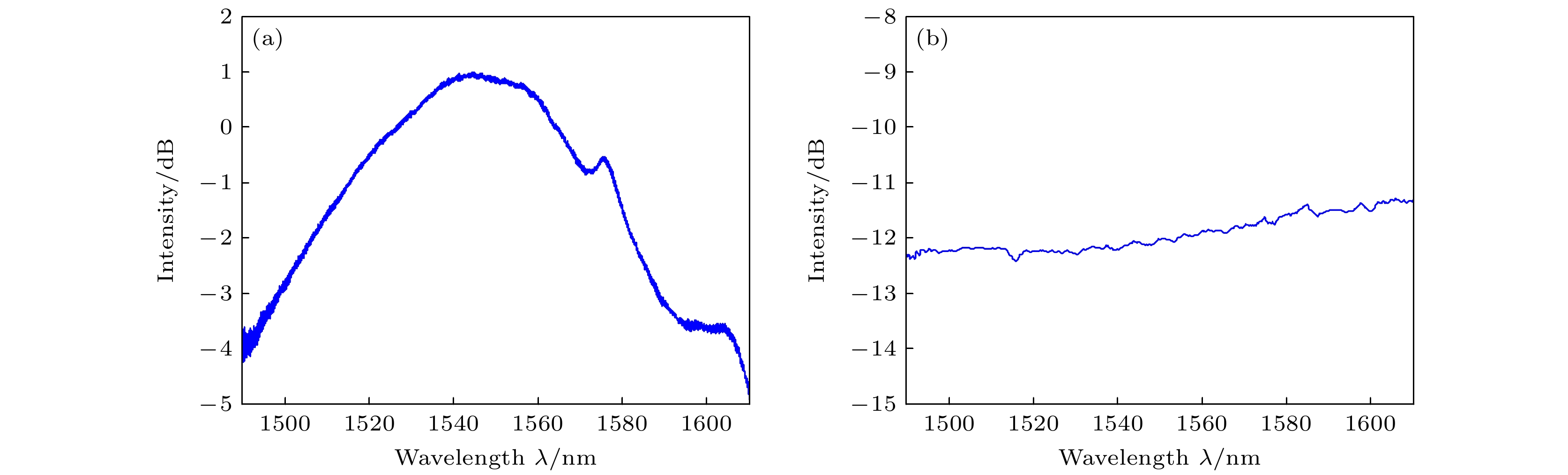
    图 4  (a) LP11模式耦合器中LP11模式与基模相对功率比随波长的变化; (b) LP21模式耦合器中LP21模式与基模相对功率随波长的变化

    Figure 4.  (a) Relative power of LP11 mode to fundamental mode in LP11 mode coupler varies with wavelength; (b) relative power of LP21 mode to fundamental mode in LP21 mode coupler varies with wavelength.

    图 5  一阶OAM模式锁模激光器以及检测装置. OIM, 光学集成模块; EDF, 掺铒光纤; DSF, 色散位移光纤; SMF, 单模光纤; MSC, 模式选择耦合器; PC, 偏振控制器; ESA, 电谱仪; OSA, 光谱仪; OSC, 示波器; SLM, 空间光调制器; Obj, 物镜; Pol, 偏振器; HWP, 半波片; CCD, 电荷耦合元件

    Figure 5.  First-order OAM mode-locked laser and detector. OIM, optical integrated module, EDF, erbium-doped fiber; DSF, dispersion-shifted fiber; SMF, single-mode fiber; MSC, mode-selective coupler; PC, polarization controller; ESA, electrical spectrum analyzer; OSA, optical spectrum analyzer; OSC, oscilloscope; SLM, spatial light modulator; Obj, objective; POL, polarizer; HWP, half-wave plate; CCD, charge-coupled device.

    图 6  一阶OAM模式锁模激光器的指标检测 (a) 激光器输出光谱; (b) 电谱仪测量下的频率成分; (c) 激光器输出锁模脉冲序列; (d) 自相关仪测量的洛伦兹拟合脉冲

    Figure 6.  Target detection of the first-order OAM mode-locked laser: (a) Output optical spectrum of laser; (b) frequency component measured by electrical spectrum analyzer; (c) output mode-locked pulse sequence of laser; (d) Lorentz mode-locked pulse measured by autocorrelator.

    图 7  二阶OAM模式锁模激光器. OIM, 光学集成模块; EDF, 掺铒光纤; DSF, 色散位移光纤; SMF, 单模光纤; MSC, 模式选择耦合器; PC, 偏振控制器

    Figure 7.  Second-order OAM mode-locked laser and detector. OIM, optical integrated module; EDF, erbium-doped fiber; DSF, dispersion-shifted fiber; SMF, single-mode fiber; MSC, mode-selective coupler; PC, polarization controller.

    图 8  二阶OAM模式锁模激光器的指标检测 (a) 激光器输出光谱; (b) 电谱仪测量下的频率成分; (c) 激光器输出锁模脉冲序列; (d) 自相关仪检测的洛伦兹拟合脉冲

    Figure 8.  Target detection of the second-order OAM mode-locked laser: (a) Output optical spectrum of laser; (b) frequency component measured by electrical spectrum analyzer; (c) output mode-locked pulse sequence of laser; (d) Lorentz fitting pulse measured by autocorrelator.

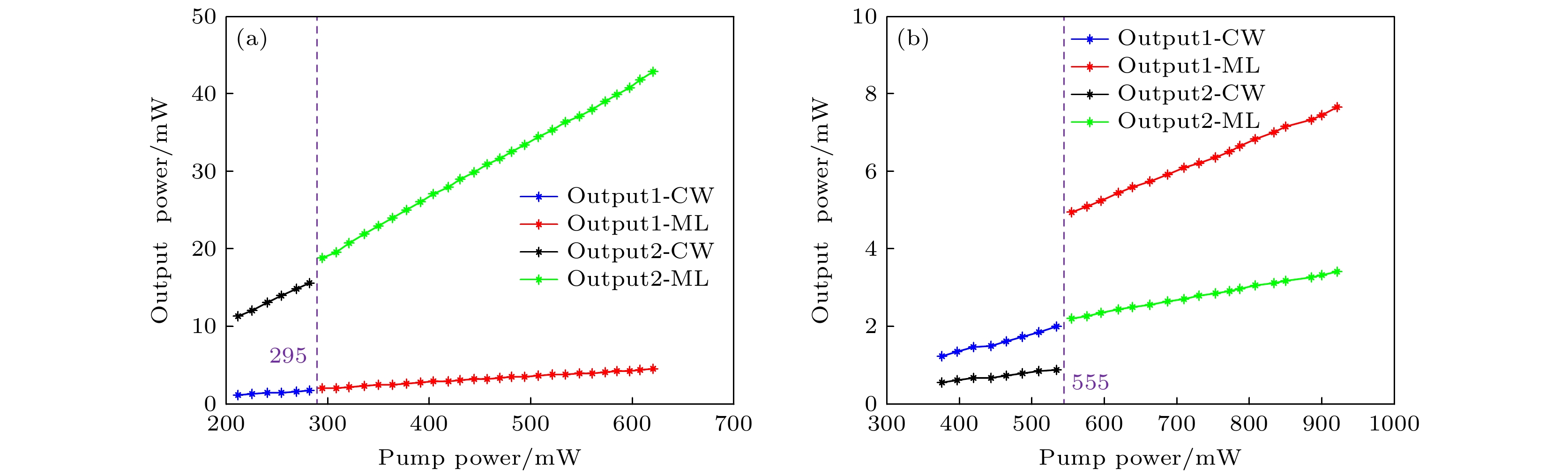
    图 9  (a) 一阶OAM模式激光器输出功率与泵浦功率之间的函数关系; (b) 二阶OAM模式激光器输出功率与泵浦功率之间的函数关系

    Figure 9.  (a) Functional relationship between the output power of the first-order OAM-mode laser and the pump power; (b) functional relationship between the output power of the second-order OAM-mode laser and the pump power.

    图 10  一阶和二阶模式激光器输出模场 (a) {\text{LP}}_{11}^{{\text{even}}}模式; (b) {\text{LP}}_{11}^{{\text{odd}}}模式; (c) {\text{LP}}_{21}^{{\text{even}}} 模式; (d) {\text{LP}}_{21}^{{\text{odd}}}模式; (e) OAM–1模式; (f) OAM+1模式; (g) OAM–2模式; (h) OAM+2模式; (i)—(l) 分别代表着图(e)—(h)经过空间光调制器上加载的柱透镜相位调制后衍射的模场

    Figure 10.  Output mode fields of first-order mode and second-order mode laser: (a) {\text{LP}}_{11}^{{\text{even}}} mode; (b) {\text{LP}}_{11}^{{\text{odd}}}mode; (c) {\text{LP}}_{21}^{{\text{even}}}mode; (d) {\text{LP}}_{21}^{{\text{odd}}}mode; (e) OAM–1 mode; (f) OAM+1 mode; (g) OAM–2 mode; (h) OAM+2 mode; (i)–(l) represent the mode fields of panels (e)–(h) diffracted by the spatial light modulator loading phase of the cylindrical lens.

    表 1  当前其他激光器性能和指标与本文激光器的比较

    Table 1.  Performance and index of other lasers are compared with the laser in this paper.

    参考文献/模式耦合器 工作机制 重复频率 中心波长/nm 输出光谱宽度/nm 输出脉宽 输出功率 模式
    [31]/OSS 锁模 13.6 MHz 1550.5 0.34 6.87 ps TE01, TM01
    [27]/FBT 锁模 36.1 MHz 1547.4 56.5 273 fs 5.6 mW OAM±1
    1545.0 67.6 140 fs OAM±2
    [32]/FBT 锁模 26 MHz 1045.0 14 75 mW LP11
    15.5 65 mW LP21
    18 16 mW LP02
    [33]/LPFG 锁模 9.83 MHz 1030.0 5 168 ps 15 mW CVB
    [34]/LPFG QSW 30.7 kHz 1548.2 0.4 5.2 μs 1.3 μW OAM±3
    [35]/FBG 锁模 10.16 MHz 1549.4 0.08 52.87 ps 17.16 mW OAM0, OAM±1
    [36]/AIFG 锁模 4.835 MHz 1532.9 <0.1 400 ps 30 mW OAM±1
    [37]/AIFG 锁模 25 MHz 1560.0 10 384 fs OAM±1
    [38]/Space 锁模 33 MHz 1030.0 18 87 fs 108 mW OAM±1
    本文/FBT 锁模 114 MHz 1550.0 101 100 98 fs 40 mW OAM±1
    115 MHz 100 60 fs 4 mW OAM±2
    DownLoad: CSV
  • [1]

    Allen L, Beijersbergen M W, Spreeuw R J C, Woerdman J P 1992 Phys. Rev. A 45 8185Google Scholar

    [2]

    Wen Y, Chremmos I, Chen Y, Zhu G, Zhang J, Zhu J, Zhang Y, Liu J, Yu S 2020 Optica 7 254Google Scholar

    [3]

    Leach J, Jack B, Romero J, Jha A K, Yao A M, Frank-Arnold S, Ireland D G, Boyd R W, Barnett S M, Padgett M J 2010 Science 329 662Google Scholar

    [4]

    Grier D 2003 Nature 424 810Google Scholar

    [5]

    Beijersbergen M W, Coerwinkel R P C, Kristensen M, Woerdman J P 1994 Opt. Commun. 112 321Google Scholar

    [6]

    Poynting J H 1909 Proc. R. Soc. London, Ser. A 82 560Google Scholar

    [7]

    Marrucci L, Karimi E, Slussarenko S, Piccirillo B, Santamato E, Nagali E, Sciarrino, F 2011 J. Opt. 13 064001Google Scholar

    [8]

    Zhao Z, Wang J, Li S, Willner A E 2013 Opt. Lett. 38 932Google Scholar

    [9]

    Chen Y, Fang Z X, Ren Y X, Gong L, Lu R D 2015 Appl. Opt. 54 8030Google Scholar

    [10]

    Li S, Mo Q, Hu X, Du C, Wang J 2015 Opt. Lett. 40 4376Google Scholar

    [11]

    Zhang W, Wei K, Huang L, Mao D, Jiang B, Gao F, Zhao J 2016 Opt. Express 24 19278Google Scholar

    [12]

    Shao L, Liu S, Zhou M, Huang Z, Bao W, Bai Z, Wang Y 2021 Opt. Express 29 43371Google Scholar

    [13]

    Li Y J, Jin L, Wu H, Gao S C, Feng Y H, Li Z H 2017 IEEE Photonics J. 9 7200909Google Scholar

    [14]

    Han Y, Liu Y G, Wang Z, Huang W, Chen L, Zhang H W, Yang K 2018 Nanophotonics 7 287Google Scholar

    [15]

    Wu H, Gao S, Huang B, Feng Y, Huang X, Liu W, Li Z 2017 Opt. Lett. 42 5210Google Scholar

    [16]

    Detani T, Zhao H, Wang P, Suzuki T, Li H 2021 Opt. Lett. 46 949Google Scholar

    [17]

    He X, Tu J, Wu X, Gao S, Shen L, Hao C, Li Z 2020 Opt. Lett. 45 3621Google Scholar

    [18]

    Pidishety S, Khudus M I M A, Gregg P, Ramachandran S, Srinivasan B, Brambilla G 2016 Conference on Lasers and Electro-Optics (CLEO) San Jose, CA, June 5–10, 2016 pSTu1F.2

    [19]

    Li J, Ueda K, Musha M, Zhong L, Shirakawa A 2008 Opt. Lett. 33 2686Google Scholar

    [20]

    Lin D, Xia K, Li J, Li R, Ueda K, Li G, Li X 2010 Opt. Lett. 35 2290Google Scholar

    [21]

    Lin D, Xia K, Li R, Li X, Li G, Ueda K, Li J 2010 Opt. Lett. 35 3574Google Scholar

    [22]

    Gui L, Wang C, Ding F, Chen H, Xiao X, Bozhevolnyi S, Zhang X, Xu K 2023 ACS Photonics 10 623

    [23]

    Zhou N, Liu J, Wang J 2018 Sci. Rep. 8 11394Google Scholar

    [24]

    Zhao Y, Wang T, Mao C, Yan Z, Liu Y, Wang T 2018 IEEE Photonics Technol. Lett. 30 752Google Scholar

    [25]

    Toyoda K, Miyamoto K, Aoki N, Morita R, Omatsu T 2012 Nano Lett. 12 3645Google Scholar

    [26]

    Zhang Z, Wei W, Tang L, Yang J, Guo J, Ding L, Li Y 2018 Chin. Opt. Lett. 16 110501Google Scholar

    [27]

    Wang T, Wang F, Shi F, Pang F, Huang S, Wang T, Zeng X 2017 J. Lightwave Technol. 35 2161Google Scholar

    [28]

    Deng D, Zhan L, Gu Z, Gu Y, Xia Y 2009 Opt. Express 17 4284Google Scholar

    [29]

    Park K, Song K, Kim Y, Lee J, Kim B 2016 Opt. Express 24 3543Google Scholar

    [30]

    Zhou H, Dong J, Wang J, Li S, Cai X, Yu S, Zhang X 2017 IEEE Photonics Technol. Lett. 29 86Google Scholar

    [31]

    Mao D, Feng T, Zhang W, Lu H, Jiang Y, Li P, Jiang B, Sun Z, Zhao J 2017 Appl. Phys. Lett. 110 021107Google Scholar

    [32]

    Huang Y, Shi F, Wang T, Liu X, Zeng X, Pang F, Wang T, Zhou P 2018 Opt. Express 26 19171Google Scholar

    [33]

    Tao R, Li H, Zhang Y, Yao P, Xu L, Gu C, Zhan Q 2020 Opt. Laser Technol. 123 105945Google Scholar

    [34]

    Xiao R, Tu J, Li Wei, Gao S, Wen T, Du C, Zhou J, Zhang B, Liu W, Li Z 2022 Opt. Express 30 12605Google Scholar

    [35]

    Jiang X, Yao J, Zhang S, Wang A, Zhan Q 2022 Appl. Phys. Lett. 121 131101Google Scholar

    [36]

    Zhang W, Wei K, Mao D, Wang H, Gao F, Huang L, Mei T, Zhao J 2017 Opt. Lett. 42 454Google Scholar

    [37]

    Lu J, Shi F, Meng L, Zhang L, Teng L, Luo Z, Yan P, Pang F, Zeng X 2020 Photonics Res. 8 1203Google Scholar

    [38]

    Hu H, Chen Z, Cao Q, Zhan Q 2023 IEEE Photonics J. 15 1Google Scholar

    [39]

    Xue X, Jiang Q, Pang F, Wen J, Chen W, Zeng X, Zhang L, Wei H, Wang T 2023 Opt. Express 31 24623Google Scholar

    [40]

    Fu S, Zhai Y, Zhang J, Liu X, Song R, Zhou H, Gao C 2022 Adv. Photonics Nexus 1 016003

  • [1] Chen Bo, Liu Jin, Li Jun-Tao, Wang Xue-Hua. Research progress of integrated quantum light sources with orbital angular momentum. Acta Physica Sinica, 2024, 73(16): 164204. doi: 10.7498/aps.73.20240791
    [2] Zhang Zhuo, Zhang Jing-Feng, Kong Ling-Jun. Orbital angular momentum splitter of light based on beam displacer. Acta Physica Sinica, 2024, 73(7): 074201. doi: 10.7498/aps.73.20231874
    [3] Zhao Li-Juan, Jiang Huan-Qiu, Xu Zhi-Niu. Helically twisted double-cladding-three-core photonic crystal fiber for generation of orbital angular momentum. Acta Physica Sinica, 2023, 72(13): 134201. doi: 10.7498/aps.72.20222405
    [4] Wu Hang, Chen Liao, Shu Xue-Wen, Zhang Xin-Liang. Generation of all-fiber third-order orbital angular momentum modes based on femtosecond laser processing of long-period grating. Acta Physica Sinica, 2023, 72(4): 044201. doi: 10.7498/aps.72.20221928
    [5] Liu Rui-Xi, Ma Lei. Effects of ocean turbulence on photon orbital angular momentum quantum communication. Acta Physica Sinica, 2022, 71(1): 010304. doi: 10.7498/aps.71.20211146
    [6] Zhao Li-Juan, Zhao Hai-Ying, Xu Zhi-Niu. Design of photonic crystal fiber amplifier based on stimulated Brillouin amplification for orbital angular momentum. Acta Physica Sinica, 2022, 71(7): 074206. doi: 10.7498/aps.71.20211909
    [7] Jiang Ji-Heng, Yu Shi-Xing, Kou Na, Ding Zhao, Zhang Zheng-Ping. Beam steering of orbital angular momentum vortex wave based on planar phased array. Acta Physica Sinica, 2021, 70(23): 238401. doi: 10.7498/aps.70.20211119
    [8] Gao Xi, Tang Li-Guang. Wideband and high efficiency orbital angular momentum generator based on bi-layer metasurface. Acta Physica Sinica, 2021, 70(3): 038101. doi: 10.7498/aps.70.20200975
    [9] Cui Can, Wang Zhi, Li Qiang, Wu Chong-Qing, Wang Jian. Modulation of orbital angular momentum in long periodchirally-coupled-cores fiber. Acta Physica Sinica, 2019, 68(6): 064211. doi: 10.7498/aps.68.20182036
    [10] Fan Rong-Hua, Guo Bang-Hong, Guo Jian-Jun, Zhang Cheng-Xian, Zhang Wen-Jie, Du Ge. Entangled W state of multi degree of freedom system based on orbital angular momentum. Acta Physica Sinica, 2015, 64(14): 140301. doi: 10.7498/aps.64.140301
    [11] Qin Peng, Song You-Jian, Hu Ming-Lie, Chai Lu, Wang Qing-Yue. Timing synchronization based on mode-locked fiber lasers with attosecond timing jitter. Acta Physica Sinica, 2015, 64(22): 224209. doi: 10.7498/aps.64.224209
    [12] Fu Dong-Zhi, Jia Jun-Liang, Zhou Ying-Nan, Chen Dong-Xu, Gao Hong, Li Fu-Li, Zhang Pei. Realisation of orbital angular momentum sorter of photons based on sagnac interferometer. Acta Physica Sinica, 2015, 64(13): 130704. doi: 10.7498/aps.64.130704
    [13] Ke Xi-Zheng, Chen Juan, Yang Yi-Ming. Study on orbital angular momentum of Laguerre-Gaussian beam in a slant-path atmospheric turbulence. Acta Physica Sinica, 2014, 63(15): 150301. doi: 10.7498/aps.63.150301
    [14] Li Tie, Chen Juan, Ke Xi-Zheng. Study of orbital angular momentum entangled photons entanglement in atmospheric channel. Acta Physica Sinica, 2012, 61(12): 124208. doi: 10.7498/aps.61.124208
    [15] Qi Xiao-Qing, Gao Chun-Qing, Xin Jing-Tao, Zhang Ge. Experimental study of 8-bits information transmission system based on orbital angular momentum of light beams. Acta Physica Sinica, 2012, 61(17): 174204. doi: 10.7498/aps.61.174204
    [16] Ke Xi-Zheng, Nu Ning, Yang Qin-Ling. Research of transmission characteristics of single-photon orbital angular momentum. Acta Physica Sinica, 2010, 59(9): 6159-6163. doi: 10.7498/aps.59.6159
    [17] Lü Hong, Ke Xi-Zheng. Scattering of a beam with orbital angular momentum by a single sphere. Acta Physica Sinica, 2009, 58(12): 8302-8308. doi: 10.7498/aps.58.8302
    [18] Su Zhi-Kun, Wang Fa-Qiang, Lu Yi-Qun, Jin Rui-Bo, Liang Rui-Sheng, Liu Song-Hao. Study on quantum cryptography using orbital angular momentum states of photons. Acta Physica Sinica, 2008, 57(5): 3016-3021. doi: 10.7498/aps.57.3016
    [19] Gao Ming-Wei, Gao Chun-Qing, Lin Zhi-Feng. Generation of twisted stigmatic beam and transfer of orbital angular momentum during the beam transformation. Acta Physica Sinica, 2007, 56(4): 2184-2190. doi: 10.7498/aps.56.2184
    [20] Gao Ming-Wei, Gao Chun-Qing, He Xiao-Yan, Li Jia-Ze, Wei Guang-Hui. Rotation of particles by using the beamwith orbital angular momentum. Acta Physica Sinica, 2004, 53(2): 413-417. doi: 10.7498/aps.53.413
  • 期刊类型引用(0)

    其他类型引用(1)

Metrics
  • Abstract views:  3976
  • PDF Downloads:  92
  • Cited By: 1
Publishing process
  • Received Date:  03 July 2023
  • Accepted Date:  03 September 2023
  • Available Online:  08 October 2023
  • Published Online:  05 January 2024

/

返回文章
返回