


-
Traditionally, ion microbeam is produced by focusing or/and collimating to reduce the beam size to submicron level. The traditional setup for producing the microbeam consists of an expensive focusing and collimating system with a large space, based on electromagnetic fields. Meanwhile, the microbeam obtained through pure collimation of metal micro-tubes is limited by the fabrication processing, i.e. the size of beam spot is largely limited to a few microns and its manufacture is not as simple as that of a glass capillary. Inspired by early studies of the guiding effect, the use of inexpensive and easy-to-make glass capillaries as the tool for ion external microbeam production has become a new direction. In this work, we use a glass capillary with an open outlet (108 μm in diameter), which serves as a vacuum differential and collimating component, to produce a 2.5 MeV-proton microbeam directly from the linear accelerator into the atmosphere for measurements. We measure the beam spot diameter and energy distribution of the microbeam as a function of the tilt angle of the capillary. We also conduct calculations and ion trajectory analysis on the scattering process of 2.5 MeV protons on the inner walls. The measurement results show that when the tilt angle is around 0°, there are a direct transmission part that maintains the initial incident energy, and a scattering part with the energy loss in the microbeam. It is found that the proportion of directly transmitted protons and the beam spot size are highest near zero tilt angle. As the tilt angle increases, the beam spot diameter decreases; when the tilt angle is greater than the geometric angle, all the microbeams come from the scattering with the energy loss. The simulation combined with the ion trajectory analysis based on the scattering process can explain the experimental results. It is found that the large angle scattering determines the entire external microbeam spot, and the central region of the beam spot is composed of directly penetrating ions, whose size is determined by the geometric shape of the glass capillary, i.e. the outlet diameter and aspect ratio. The natural advantage of producing external micobeames easily and inexpensively through glass capillaries is their relative safety and stable operation, and the last but not least point is to simply locate the microbeams on the sample without complex diagnostic tools. The microbeams are expected to be widely used in fields such as radiation biology, medicine, and materials. -
Keywords:
- ions external microbeam /
- MeV protons /
- conical glass capillary
[1] Grime G W, Abraham M H, Marsh M A 2001 Nucl. Instrum. Methods Phys. Res. Sect. B 181 66
 Google Scholar
[2] 窦彦昕 2018 博士学位论文(哈尔滨: 哈尔滨工业大学)
Dou Y X 2018 Ph. D. Dissertation (Harbin: Harbin Institute of Technology
[3] Stolterfoht N, Bremer J H, Hoffmann V, Hellhammer R, Fink D, Petrov A, Sulik B 2002 Phys. Rev. Lett. 88 133201
Google Scholar
[4] Nebiki T, Yamamoto T, Narusawa T 2003 J. Vac. Sci. Technol. A 21 1671
Google Scholar
[5] Skog P, Zhang H, Schuch R 2008 Phys. Rev. Lett. 101 223202
Google Scholar
[6] Zhang H Q, Skog P, Schuch R 2010 Phys. Rev. A 82 052901
Google Scholar
[7] Cassimi A, Muranaka T, Maunoury L, Lebius H, Manil B, Huber B A, Ikeda T, Kanai Y, Kojima T M, Iwai Y, Kambara T, Yamazaki Y, Nebiki T, Narusawa T 2008 Int. J. Nanotechnol. 5 809
Google Scholar
[8] Cassimi A, Ikeda T, Maunoury L, Zhou C L, Guillous S, Mery A, Lebius H, Benyagoub A, Grygiel C, Khemliche H, Roncin P, Merabet H, Tanis J A 2012 Phys. Rev. A 86 062902
Google Scholar
[9] Chen J, Xue Y L, Liu J L, Wu Y H, Ruan F F, Wang W, Yu D Y, Cai X H 2012 Nucl. Instrum. Methods Phys. Res. , Sect. B 281 26
Google Scholar
[10] Mátéfi-Tempfli S, Mátéfi-Tempfli M, Piraux L, Juhász Z, Biri S, Fekete É, Iván I, Gáll F, Sulik B, Víkor Gy, Pálinkás J, Stolterfoht N 2006 Nanotechnology 17 3915
Google Scholar
[11] Skog P, Soroka I L, Johansson A, Schuch R 2007 Nucl. Instrum. Metods Phys. Res. Sect. B 258 145
Google Scholar
[12] Wang Y Y, Li D H, Zhao Y T, Xiao G Q, Xu Z F, Li F L, Chen X M 2009 J. Phys. Conf. Ser. 194 132032
Google Scholar
[13] Stolterfoht N, Hellhammer R, Sulik B, Juhász Z, Bayer V, Trautmann C, Bodewits E, Hoekstra R 2011 Phys. Rev. A 83 062901
Google Scholar
[14] Wang X, Zhao Y T, Wang Y Y, Cheng R, Li D H, Zhang S F, Xiao G Q 2011 Phys. Scr. 2011 014046
Google Scholar
[15] Juhász Z, Kovács S T S, Herczku P, Rácz R, Biri S, Rajta I, Gál G A B, Szilasi S Z, Pálinkás J, Sulik B 2012 Nucl. Instrum. Methods Phys. Res., Sect. B 279 177
Google Scholar
[16] Sahana M B, Skog P, Vikor G, Kumar R T R, Schuch R 2006 Phys. Rev. A 73 040901
Google Scholar
[17] Sun G Z, Chen X M, Wang J, Chen Y F, Xu J K, Zhou C L, Shao J X, Cui Y, Ding B W, Yin Y Z, Wang X A, Lou F J, Lü X Y, Qiu X Y, Jia J J, Chen L, Xi F Y, Chen Z C, Li L T, Liu Z Y 2009 Phys. Rev. A 79 052902
Google Scholar
[18] Chen L, Guo Y L, Jia J J, Zhang H Q, Cui Y, Shao J X, Yin Y Z, Qiu X Y, Lü X Y, Sun G Z, Wang J, Chen Y F, Xi F Y, Chen X M 2011 Phys. Rev. A 84 032901
Google Scholar
[19] Feng D, Shao J X, Zhao L, Ji M C, Zou X R, Wang G Y, Ma Y L, Zhou W, Zhou H, Li Y, Zhou M, Chen X M 2012 Phys. Rev. A 85 064901
Google Scholar
[20] Zhang Q, Liu Z L, Li P F, Jin B, Song G Y, Jin D K, Niu B, Wei L, Ha S, Xie Y M, Ma Y, Wan C L, Cui Y, Zhou P, Zhang H Q, Chen X M 2018 Phys. Rev. A 97 042704
Google Scholar
[21] Milosavljević A R, Víkor G, Pešić Z D, Kolarž P, Šević D, Marinković B P, Mátéfi-Tempfli S, Mátéfi-Tempfli M, Piraux L 2007 Phys. Rev. A 75 030901
Google Scholar
[22] Das S, Dassanayake B S, Winkworth M, Baran J L, Stolterfoht N, Tanis J A 2007 Phys. Rev. A 76 042716
Google Scholar
[23] Keerthisinghe D, Dassanayake B S, Wickramarachchi S J, Stolterfoht N, Tanis J A 2015 Phys. Rev. A 92 012703
Google Scholar
[24] Schiessl K, Tőkési K, Solleder B, Lemell C, Burgdörfer J 2009 Phys. Rev. Lett. 102 163201
Google Scholar
[25] Stolterfoht N, Tanis J 2018 Nucl. Instrum. Metods Phys. Res. Sect. B 421 32
Google Scholar
[26] Dassanayake B S, Das S, Bereczky R J, Tőkési K, Tanis J A 2010 Phys. Rev. A 81 020701
Google Scholar
[27] Dassanayake B S, Bereczky R J, Das S, Ayyad A, Tökési K, Tanis J A 2011 Phys. Rev. A 83 012707
Google Scholar
[28] 万城亮, 李鹏飞, 钱立冰, 靳博, 宋光银, 高志民, 周利华, 张琦, 宋张勇, 杨治虎, 邵剑雄, 崔莹, Reinhold Schuch, 张红强, 陈熙萌 2016 物理学报 65 204103
Google Scholar
Wan C L, Li P F, Qian L B, Jin B, Song G Y, Gao Z M, Zhou L H, Zhang Q, Song Z Y, Yang Z H, Shao J X, Cui Y, Reinhold S, Zhang H Q, Chen X M 2016 Acta Phys. Sin. 65 204103
Google Scholar
[29] 钱立冰, 李鹏飞, 靳博, 靳定坤, 宋光银, 张琦, 魏龙, 牛犇, 万成亮, 周春林, Arnold Milenko Mscrir, Max Dobeli, 宋张勇, 杨治虎, Reinhold Schuch, 张红强, 陈熙萌 2017 物理学报 66 124101
Google Scholar
Qian L B, Li P F, Jin B, Jin D K, Song G Y, Zhang Q, Wei L, Niu B, Wan C L, Zhou C L, Arnold Milenko M, Max D, Song Z Y, Yang Z H, Reinhold S, Zhang H Q, Chen X M 2017 Acta Phys. Sin. 66 124101
Google Scholar
[30] Nguyen H D, Wulfkühler J P, Heisig J, Tajmar M 2021 Sci. Rep. 11 8345
Google Scholar
[31] 李鹏飞, 袁华, 程紫东, 钱立冰, 刘中林, 靳博, 哈帅, 万城亮, 崔莹, 马越, 杨治虎, 路迪, Reinhold Schuch, 黎明, 张红强, 陈熙萌 2022 物理学报 71 074101
Google Scholar
Li P F, Yuan H, Cheng Z D, Qian L B, Liu Z L, Jin B, Ha S, Wan C L, Cui Y, Ma Y, Yang Z H, Lu D, Reinhold S, Li M, Zhang H Q, Chen X M 2022 Acta Phys. Sin. 71 074101
Google Scholar
[32] 李鹏飞, 袁华, 程紫东, 钱立冰, 刘中林, 靳博, 哈帅, 张浩文, 万城亮, 崔莹, 马越, 杨治虎, 路迪, Reinhold Schuch, 黎明, 张红强, 陈熙萌 2022 物理学报 71 084104
Google Scholar
Li P F, Yuan H, Cheng Z D, Qian L B, Liu Z L, Jin B, Ha S, Zhang H W, Wan C L, Cui Y, Ma Y, Yang Z H, Lu D, Reinhold S, Li M, Zhang H Q, Chen X M 2022 Acta Phys. Sin. 71 084104
Google Scholar
[33] Oshima N, Iwai Y, Kojima T M, Ikeda T, Kanazawa Y, Hoshino M, Suzuki R, Yamazaki Y 2009 Mater. Sci. Forum 607 263
Google Scholar
[34] DuBois R D, Tőkési K 2012 Nucl. Instrum. Methods Phys. Res. Sect. B 279 186
Google Scholar
[35] Kojima T M, Tomono D, Ikeda T, Ishida K, Iwai Y, Iwasaki M, Matsuda Y, Matsuzaki T, Yamazaki Y 2007 J. Phys. Soc. Jpn. 76 093501
Google Scholar
[36] Tomono D, Kojima T M, Ishida K, Ikeda T, Iwai Y, Tokuda M, Kanazawa Y, Matsuda Y, Matsuzaki T, Iwasaki M, Yamazaki Y 2011 J. Phys. Soc. Jpn. 80 044501
Google Scholar
[37] Ikeda T, Kanai Y, Iwai Y, Kojima T M, Maeshima K, Meissl W, Kobayashi T, Nebiki T, Miyamoto S, Pokhil G P, Narusawa T, Imamoto N, Yamazaki Y 2011 Surf. Coat. Tech. 206 859
Google Scholar
[38] Ikeda T, Kanai Y, Kojima T M, Iwai Y, Kambara T, Yamazaki Y, Hoshino M, Nebiki T, Narusawa T 2006 Appl. Phys. Lett. 89 163502
Google Scholar
[39] Kowarik G, Bereczky R J, Aumayr F, Tőkési K 2009 Nucl. Instrum. Methods Phys. Res. , Sect. B 267 2277
Google Scholar
[40] Bereczky R J, Kowarik G, Aumayr F, Tőkési K 2009 Nucl. Instrum. Methods Phys. Res. Sect. B 267 317
Google Scholar
[41] Gruber E, Stolterfoht N, Allinger P, Wampl S, Wang Y, Simon M J, Aumayr F 2014 Nucl. Instrum. Methods Phys. Res. Sect. B 340 1
Google Scholar
[42] Ikeda T, Kojima T M, Natsume Y, Kimura J, Abe T 2016 Appl. Phys. Lett. 109 133501
Google Scholar
[43] Nebiki T, Sekiba D, Yonemura H, Wilde M, Ogura S, Yamashita H, Matsumoto M, Fukutani K, Okano T, Kasagi J, Iwamura Y, Itoh T, Kuribayashi S, Matsuzaki H, Narusawa T 2008 Nucl. Instrum. Methods Phys. Res. Sect. B 266 1324
Google Scholar
[44] Hespeels F, Tonneau R, Ikeda T, Lucas S 2015 Nucl. Instrum. Methods Phys. Res. Sect. B 362 72
Google Scholar
[45] Simon M J, Döbeli M, Müller A M, Synal H A 2012 Nucl. Instrum. Methods Phys. Res. Sect. B 273 237
Google Scholar
[46] Ikeda T, Ikekame M, Hikima Y, Mori M, Kawamura S, Minowa T, Jin W G 2020 Nucl. Instrum. Methods Phys. Res. Sect. B 470 42
Google Scholar
[47] Iwai Y, Ikeda T, Kojima T M, Yamazaki Y, Maeshima K, Imamoto N, Kobayashi T, Nebiki T, Narusawa T, Pokhil G P 2008 Appl. Phys. Lett. 92 023509
Google Scholar
[48] Mäckel V, Meissl W, Ikeda T, Clever M, Meissl E, Kobayashi T, Kojima T M, Imamoto N, Ogiwara K, Yamazaki Y 2014 Rev. Sci. Instrum. 85 014302
Google Scholar
[49] Mäckel V, Puttaraksa N, Kobayashi T, Yamazaki Y 2015 Rev. Sci. Instrum. 86 085103
Google Scholar
[50] Puttaraksa N, Mäckel V, Kobayashi T, Kojima T M, Hamagaki M, Imamoto N, Yamazaki Y 2015 Nucl. Instrum. Methods Phys. Res. Sect. B 348 127
Google Scholar
[51] Ikeda T, Izumi M, Mäckel V, Kobayashi T, Bereczky R J, Hirano T, Yamazaki Y, Abe T 2015 RIKEN Accel. Prog. Rep. 48 315
[52] Ikeda T, Izumi M, Mäckel V, Kobayashi T, Ogiwara K, Hirano T, Yamazaki Y, Abe T 2014 RIKEN Accel. Prog. Rep. 47 282
[53] Kato M, Meissl W, Umezawa K, Ikeda T, Yamazaki Y 2012 Appl. Phys. Lett. 100 193702
Google Scholar
[54] Ikeda T 2020 Quantum Beam Sci. 4 22
Google Scholar
[55] 谢一鸣 2020 硕士学位论文(兰州: 兰州大学)
Xie Y M 2020 M. S. Thesis (Lanzhou: Lanzhou University
[56] He T, Wan C, Liu Z, Zhang H, Lu L 2023 JINST 18 P05034
Google Scholar
[57] Rana M A 2018 Nucl. Instrum. Methods Phys. Res. Sect. A 910 121
Google Scholar
[58] Computer code SRIM, version-2013[EB/OL] Ziegler J F http://www.srim.org/ [2024-1-1]
-
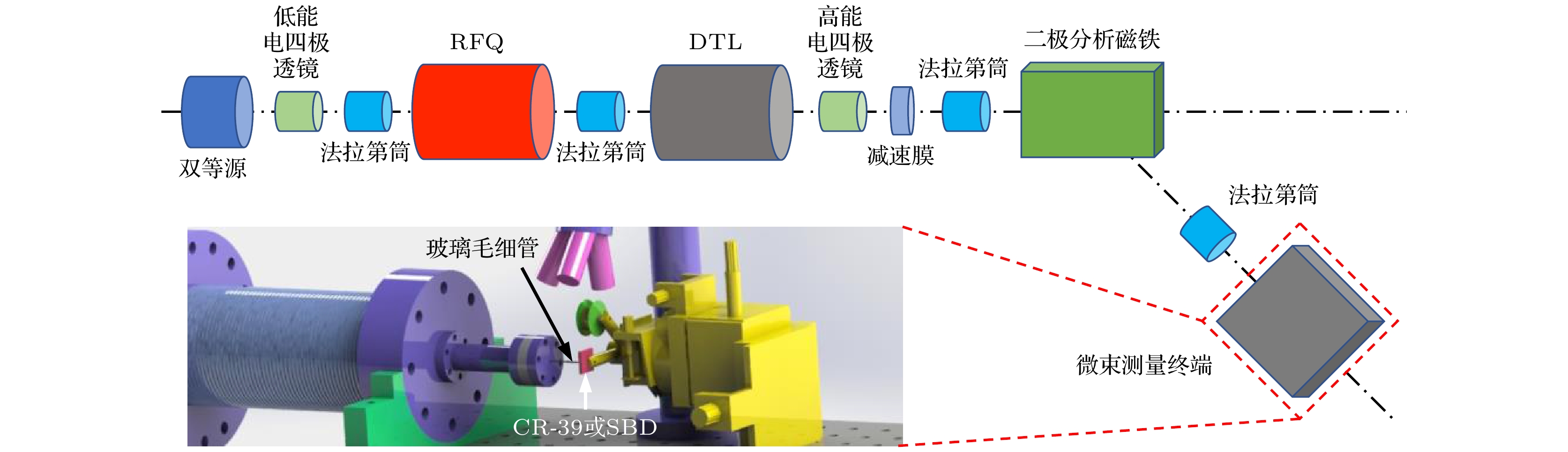
图 1 外束微束产生装置及测量终端示意图, 虚线框为外束微束测量终端
Figure 1. Schematic drawing of external microbeam production device and measurement terminal, dashed box is external microbeam measurement terminal.
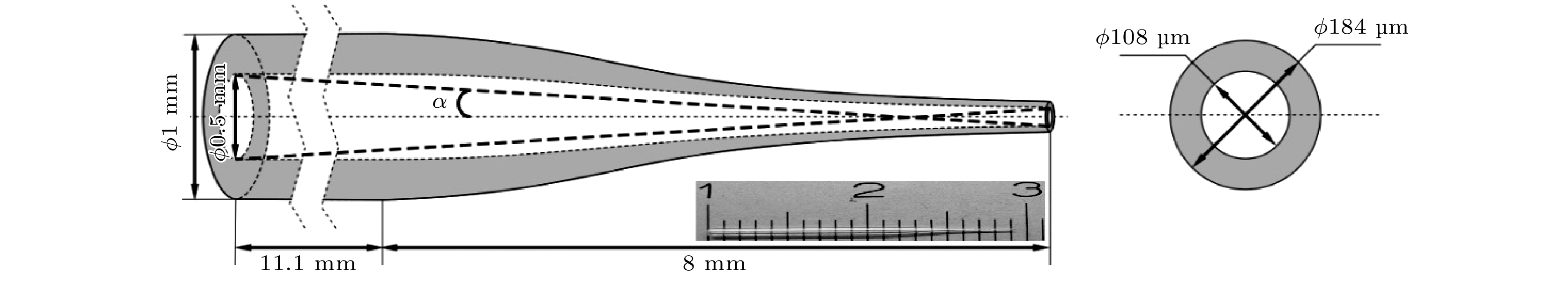
图 2 玻璃毛细管整体示意图(左)和出口截面示意图(右), 插入图为玻璃毛细管实物图
Figure 2. Schematic drawing of the glass capillary, left is overall, α indicating the geometric flare angle of the glass capillary, right is outlet cross section, and the insert shows the photograph of the glass capillary.
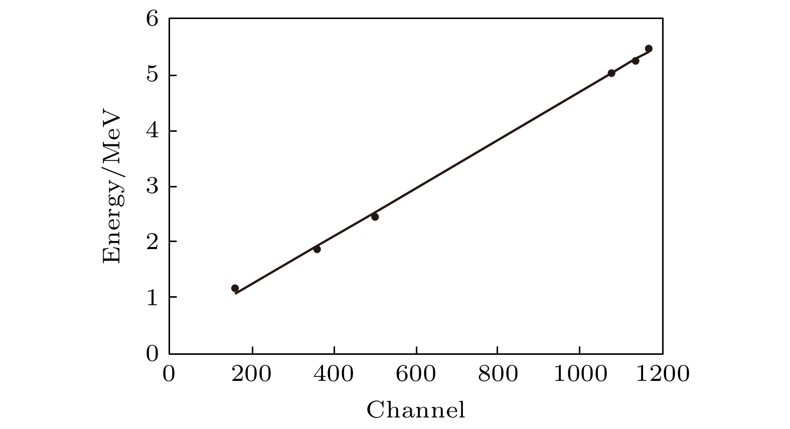
图 3 金硅面垒探测器的能量刻度曲线
Figure 3. Energy calibration curve of the surface barrier detector.
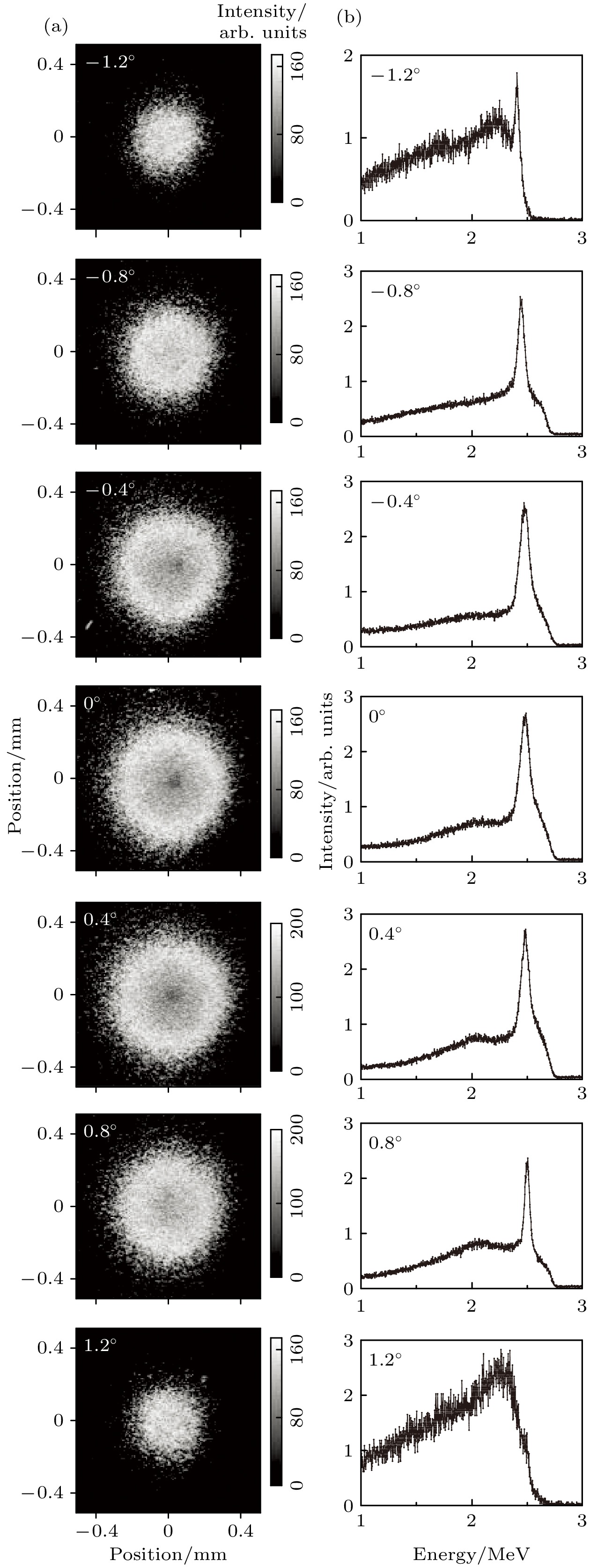
图 4 玻璃毛细管在不同倾角下外束微束的束斑图(a)和能谱(b)
Figure 4. Beam profiles (a) and energy spectra (b) of the external microbeam at distance from the outlet of the glass capillary as 1 mm, according to various tilt angles of the glass capillary.
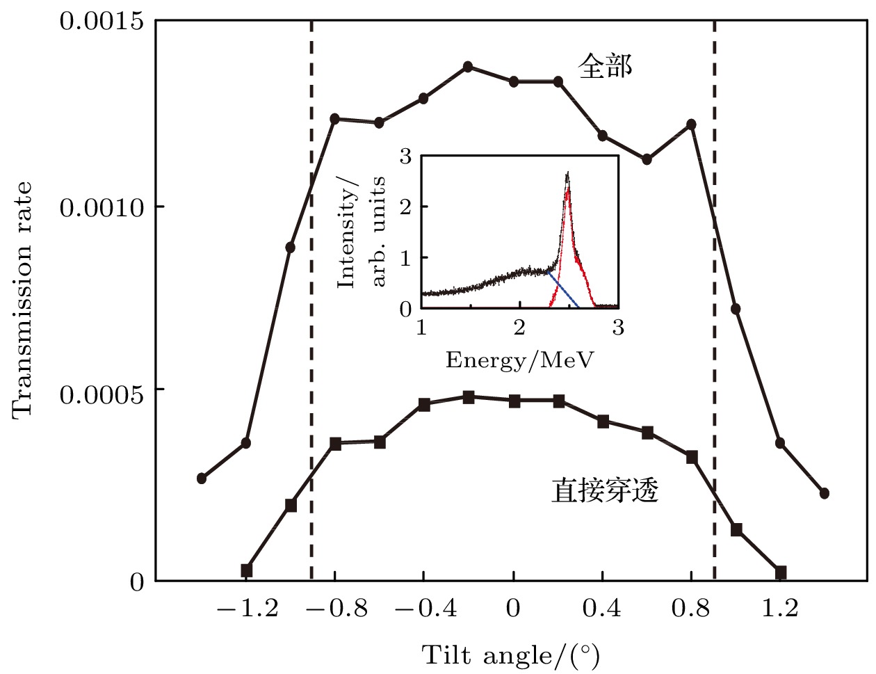
图 5 玻璃毛细管在不同倾角下外束微束的全部穿透率(圆形标记)和直接穿透穿透率(正方形标记). 插图为0°倾角下实验测得的外束微束能谱(黑色), 解谱得到直接穿透部分(红色)和散射部分(蓝色). 左右两侧虚线间距代表玻璃毛细管的张角(0.9°)
Figure 5. Transmission rate of the total penetration (circle) and direct penetration (square) of the external microbeam, according to various tilt angles of the glass capillary. Insert: experimentally measured energy spectrum of the external microbeam at tilt angle 0°(black), the direct penetration part (red) and scattering part (blue) are obtained by deconstructing the spectrum. The distance between the dashed lines on both sides represents the geometric flare angle of the glass capillary (0.9°).
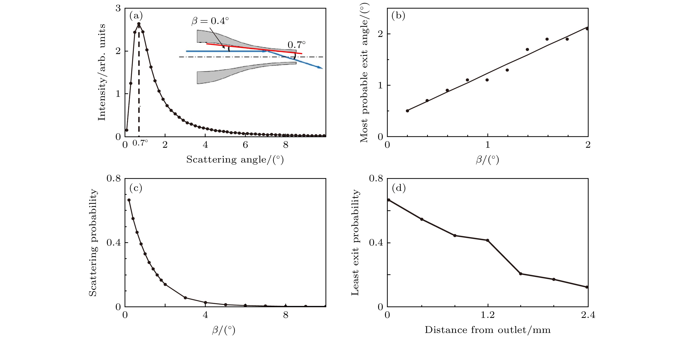
图 6 2.5 MeV质子在玻璃毛细管内的模拟结果 (a) β = 0.4°时的散射角分布, 此时散射离子最大概率出射角为0.7°; (b) 不同β角下的最大概率出射角; (c)不同β角下的散射概率; (d) 玻璃毛细管内侧距出口不同距离处的出射最小概率
Figure 6. Simulation of 2.5 MeV protons in the glass capillary: (a) Scattering angle distribution at an incidence angle of 0.4°, the most probability exit angle is 0.7°; (b) the most probable exit angle at different β angles; (c) scattering probability of protons at different β angles; (d) the least exit probability at different distances in the glass capillary towards the outlet.
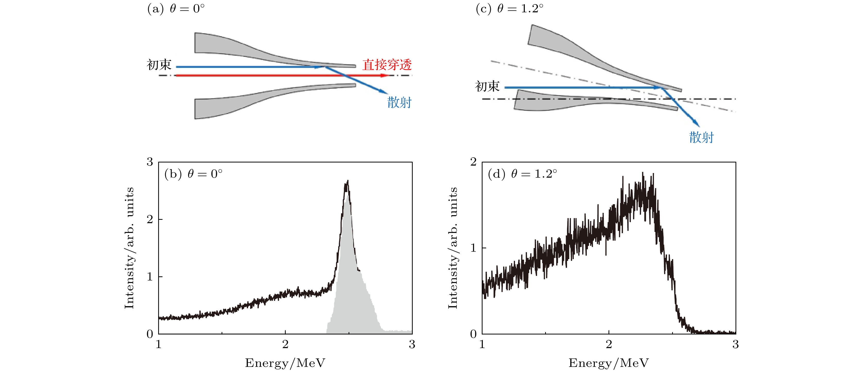
图 7 (a)倾角为0°时外束微束在玻璃管末端的出射情况示意图; (b)实验测得能谱, 黑色线为总能谱, 灰色填充部分为直接穿透能谱; (c)倾角为1.2°时直接穿透离子消失; (d)相应的能谱中直接穿透部分消失
Figure 7. (a) Schematic drawing of the external microbeam emission at the end of a glass capillary; (b) the experimentally measured energy spectrum at title angle of 0°, the red and blue lines in panel (a) represent the diret penetration and scattering part, respectively; the black line and the gray filled part represent the total energy spectrum and the direct penetration spectrum, respectively; (c) when the tilt angle is 1.2°, the directly penetrating ions disappear; (d) the directly penetrating part of the energy spectrum disappears, correspondingly.
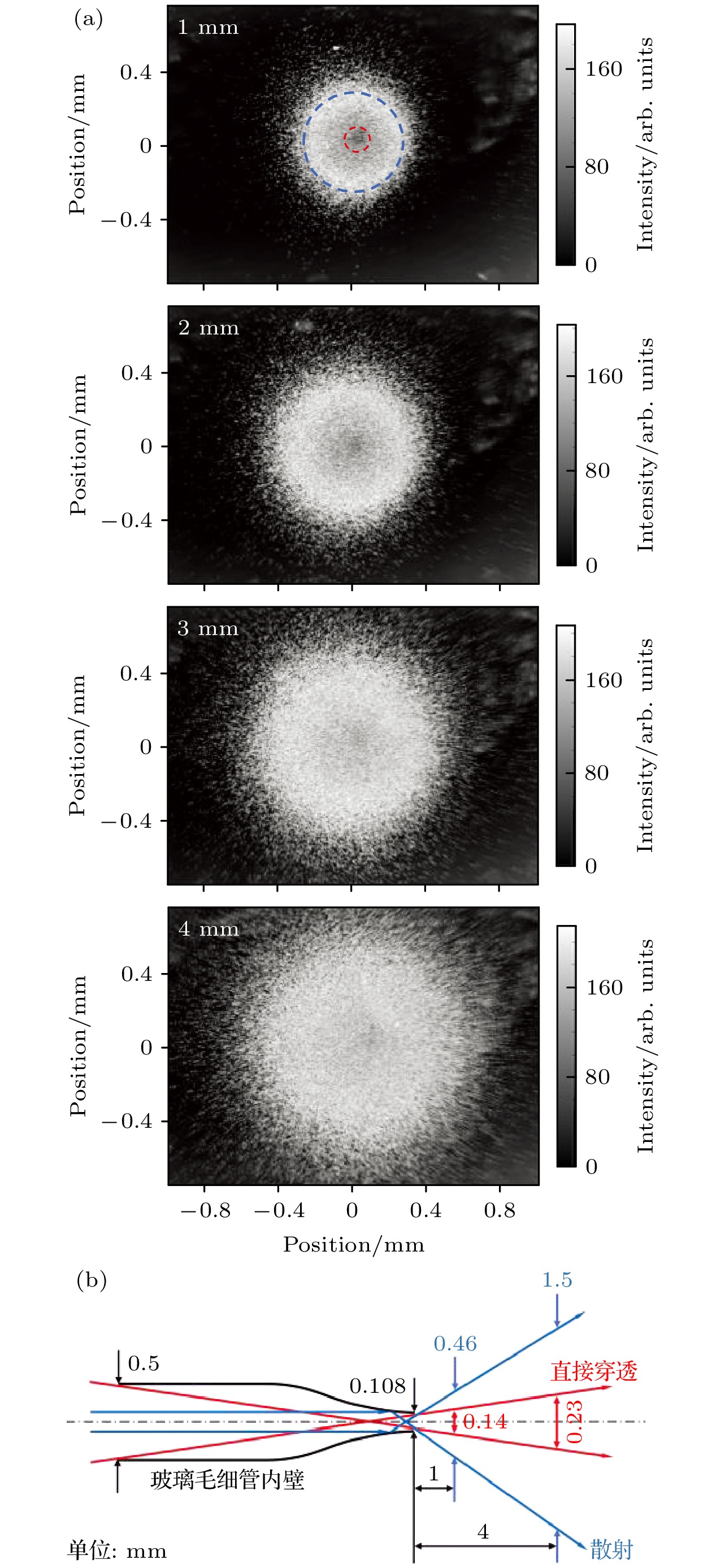
图 8 (a) 0°倾角下, 距毛细玻璃管出口不同距离处的外束微束束斑轮廓. 1 mm处束斑轮廓图中红色和蓝色虚线区域分别为直接穿透离子和散射离子在探测器上形成的束斑轮廓. (b) 0°倾角下直接穿透离子(红色)和散射离子(蓝色)分别在距玻璃毛细管出口1 mm和4 mm处探测器上形成束斑尺寸的理论示意图, 分别以1.8°张角和20°张角计算直接穿透离子和散射离子的理论最大分布直径. 距玻璃管出口1 mm和4 mm处, 直接穿透离子为140 μm和230 μm, 散射离子为460 μm和1.5 mm
Figure 8. (a) Spot profiles of the external microbeam at different distances from the outlet of the glass capillary at tilt angle of 0°. Red and blue dashed lines represent the beam spot profiles formed by directly penetrating ions and scattering ions on the detector, respectively. (b) Theoretical schematic panel (a) of the beam spot size formed by direct penetration of ions (red) and scattered ions (blue) at an tilt angle of 0° on the detector at a distance of 1 mm and 4 mm from the exit of the glass capillary, respectively. The theoretical maximum distribution diameters of direct penetrating ions and scattered ions were calculated at angles of 1.8° and 20°, respectively. At distances of 1 mm and 4 mm from the exit of the glass capilarry, the spot diameters of direct penetrating ions are 140 μm and 230 μm, while the spot diameters of the scattered ions are 460 μm and 1.5 mm.
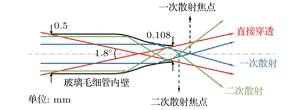
图 9 离子在玻璃毛细管内壁上以最大出射角发生一次散射(蓝色)和二次散射(绿色)示意图, 红线代表直接穿透离子. 初级和次级散射离子的焦点分别位于距离玻璃毛细管出口约3 mm和1 mm处
Figure 9. Schematic drawing of primary (blue) and secondary (green) scattering of ions at the most probability exit angle on the inner wall of the glass capillary, the red line representing direct penetration of ions. The focal points of primary and secondary scattering ions are located approximately 3 mm and 1 mm away from the glass capillary outlet, respectively.
-
[1] Grime G W, Abraham M H, Marsh M A 2001 Nucl. Instrum. Methods Phys. Res. Sect. B 181 66
Google Scholar
[2] 窦彦昕 2018 博士学位论文(哈尔滨: 哈尔滨工业大学)
Dou Y X 2018 Ph. D. Dissertation (Harbin: Harbin Institute of Technology
[3] Stolterfoht N, Bremer J H, Hoffmann V, Hellhammer R, Fink D, Petrov A, Sulik B 2002 Phys. Rev. Lett. 88 133201
Google Scholar
[4] Nebiki T, Yamamoto T, Narusawa T 2003 J. Vac. Sci. Technol. A 21 1671
Google Scholar
[5] Skog P, Zhang H, Schuch R 2008 Phys. Rev. Lett. 101 223202
Google Scholar
[6] Zhang H Q, Skog P, Schuch R 2010 Phys. Rev. A 82 052901
Google Scholar
[7] Cassimi A, Muranaka T, Maunoury L, Lebius H, Manil B, Huber B A, Ikeda T, Kanai Y, Kojima T M, Iwai Y, Kambara T, Yamazaki Y, Nebiki T, Narusawa T 2008 Int. J. Nanotechnol. 5 809
Google Scholar
[8] Cassimi A, Ikeda T, Maunoury L, Zhou C L, Guillous S, Mery A, Lebius H, Benyagoub A, Grygiel C, Khemliche H, Roncin P, Merabet H, Tanis J A 2012 Phys. Rev. A 86 062902
Google Scholar
[9] Chen J, Xue Y L, Liu J L, Wu Y H, Ruan F F, Wang W, Yu D Y, Cai X H 2012 Nucl. Instrum. Methods Phys. Res. , Sect. B 281 26
Google Scholar
[10] Mátéfi-Tempfli S, Mátéfi-Tempfli M, Piraux L, Juhász Z, Biri S, Fekete É, Iván I, Gáll F, Sulik B, Víkor Gy, Pálinkás J, Stolterfoht N 2006 Nanotechnology 17 3915
Google Scholar
[11] Skog P, Soroka I L, Johansson A, Schuch R 2007 Nucl. Instrum. Metods Phys. Res. Sect. B 258 145
Google Scholar
[12] Wang Y Y, Li D H, Zhao Y T, Xiao G Q, Xu Z F, Li F L, Chen X M 2009 J. Phys. Conf. Ser. 194 132032
Google Scholar
[13] Stolterfoht N, Hellhammer R, Sulik B, Juhász Z, Bayer V, Trautmann C, Bodewits E, Hoekstra R 2011 Phys. Rev. A 83 062901
Google Scholar
[14] Wang X, Zhao Y T, Wang Y Y, Cheng R, Li D H, Zhang S F, Xiao G Q 2011 Phys. Scr. 2011 014046
Google Scholar
[15] Juhász Z, Kovács S T S, Herczku P, Rácz R, Biri S, Rajta I, Gál G A B, Szilasi S Z, Pálinkás J, Sulik B 2012 Nucl. Instrum. Methods Phys. Res., Sect. B 279 177
Google Scholar
[16] Sahana M B, Skog P, Vikor G, Kumar R T R, Schuch R 2006 Phys. Rev. A 73 040901
Google Scholar
[17] Sun G Z, Chen X M, Wang J, Chen Y F, Xu J K, Zhou C L, Shao J X, Cui Y, Ding B W, Yin Y Z, Wang X A, Lou F J, Lü X Y, Qiu X Y, Jia J J, Chen L, Xi F Y, Chen Z C, Li L T, Liu Z Y 2009 Phys. Rev. A 79 052902
Google Scholar
[18] Chen L, Guo Y L, Jia J J, Zhang H Q, Cui Y, Shao J X, Yin Y Z, Qiu X Y, Lü X Y, Sun G Z, Wang J, Chen Y F, Xi F Y, Chen X M 2011 Phys. Rev. A 84 032901
Google Scholar
[19] Feng D, Shao J X, Zhao L, Ji M C, Zou X R, Wang G Y, Ma Y L, Zhou W, Zhou H, Li Y, Zhou M, Chen X M 2012 Phys. Rev. A 85 064901
Google Scholar
[20] Zhang Q, Liu Z L, Li P F, Jin B, Song G Y, Jin D K, Niu B, Wei L, Ha S, Xie Y M, Ma Y, Wan C L, Cui Y, Zhou P, Zhang H Q, Chen X M 2018 Phys. Rev. A 97 042704
Google Scholar
[21] Milosavljević A R, Víkor G, Pešić Z D, Kolarž P, Šević D, Marinković B P, Mátéfi-Tempfli S, Mátéfi-Tempfli M, Piraux L 2007 Phys. Rev. A 75 030901
Google Scholar
[22] Das S, Dassanayake B S, Winkworth M, Baran J L, Stolterfoht N, Tanis J A 2007 Phys. Rev. A 76 042716
Google Scholar
[23] Keerthisinghe D, Dassanayake B S, Wickramarachchi S J, Stolterfoht N, Tanis J A 2015 Phys. Rev. A 92 012703
Google Scholar
[24] Schiessl K, Tőkési K, Solleder B, Lemell C, Burgdörfer J 2009 Phys. Rev. Lett. 102 163201
Google Scholar
[25] Stolterfoht N, Tanis J 2018 Nucl. Instrum. Metods Phys. Res. Sect. B 421 32
Google Scholar
[26] Dassanayake B S, Das S, Bereczky R J, Tőkési K, Tanis J A 2010 Phys. Rev. A 81 020701
Google Scholar
[27] Dassanayake B S, Bereczky R J, Das S, Ayyad A, Tökési K, Tanis J A 2011 Phys. Rev. A 83 012707
Google Scholar
[28] 万城亮, 李鹏飞, 钱立冰, 靳博, 宋光银, 高志民, 周利华, 张琦, 宋张勇, 杨治虎, 邵剑雄, 崔莹, Reinhold Schuch, 张红强, 陈熙萌 2016 物理学报 65 204103
Google Scholar
Wan C L, Li P F, Qian L B, Jin B, Song G Y, Gao Z M, Zhou L H, Zhang Q, Song Z Y, Yang Z H, Shao J X, Cui Y, Reinhold S, Zhang H Q, Chen X M 2016 Acta Phys. Sin. 65 204103
Google Scholar
[29] 钱立冰, 李鹏飞, 靳博, 靳定坤, 宋光银, 张琦, 魏龙, 牛犇, 万成亮, 周春林, Arnold Milenko Mscrir, Max Dobeli, 宋张勇, 杨治虎, Reinhold Schuch, 张红强, 陈熙萌 2017 物理学报 66 124101
Google Scholar
Qian L B, Li P F, Jin B, Jin D K, Song G Y, Zhang Q, Wei L, Niu B, Wan C L, Zhou C L, Arnold Milenko M, Max D, Song Z Y, Yang Z H, Reinhold S, Zhang H Q, Chen X M 2017 Acta Phys. Sin. 66 124101
Google Scholar
[30] Nguyen H D, Wulfkühler J P, Heisig J, Tajmar M 2021 Sci. Rep. 11 8345
Google Scholar
[31] 李鹏飞, 袁华, 程紫东, 钱立冰, 刘中林, 靳博, 哈帅, 万城亮, 崔莹, 马越, 杨治虎, 路迪, Reinhold Schuch, 黎明, 张红强, 陈熙萌 2022 物理学报 71 074101
Google Scholar
Li P F, Yuan H, Cheng Z D, Qian L B, Liu Z L, Jin B, Ha S, Wan C L, Cui Y, Ma Y, Yang Z H, Lu D, Reinhold S, Li M, Zhang H Q, Chen X M 2022 Acta Phys. Sin. 71 074101
Google Scholar
[32] 李鹏飞, 袁华, 程紫东, 钱立冰, 刘中林, 靳博, 哈帅, 张浩文, 万城亮, 崔莹, 马越, 杨治虎, 路迪, Reinhold Schuch, 黎明, 张红强, 陈熙萌 2022 物理学报 71 084104
Google Scholar
Li P F, Yuan H, Cheng Z D, Qian L B, Liu Z L, Jin B, Ha S, Zhang H W, Wan C L, Cui Y, Ma Y, Yang Z H, Lu D, Reinhold S, Li M, Zhang H Q, Chen X M 2022 Acta Phys. Sin. 71 084104
Google Scholar
[33] Oshima N, Iwai Y, Kojima T M, Ikeda T, Kanazawa Y, Hoshino M, Suzuki R, Yamazaki Y 2009 Mater. Sci. Forum 607 263
Google Scholar
[34] DuBois R D, Tőkési K 2012 Nucl. Instrum. Methods Phys. Res. Sect. B 279 186
Google Scholar
[35] Kojima T M, Tomono D, Ikeda T, Ishida K, Iwai Y, Iwasaki M, Matsuda Y, Matsuzaki T, Yamazaki Y 2007 J. Phys. Soc. Jpn. 76 093501
Google Scholar
[36] Tomono D, Kojima T M, Ishida K, Ikeda T, Iwai Y, Tokuda M, Kanazawa Y, Matsuda Y, Matsuzaki T, Iwasaki M, Yamazaki Y 2011 J. Phys. Soc. Jpn. 80 044501
Google Scholar
[37] Ikeda T, Kanai Y, Iwai Y, Kojima T M, Maeshima K, Meissl W, Kobayashi T, Nebiki T, Miyamoto S, Pokhil G P, Narusawa T, Imamoto N, Yamazaki Y 2011 Surf. Coat. Tech. 206 859
Google Scholar
[38] Ikeda T, Kanai Y, Kojima T M, Iwai Y, Kambara T, Yamazaki Y, Hoshino M, Nebiki T, Narusawa T 2006 Appl. Phys. Lett. 89 163502
Google Scholar
[39] Kowarik G, Bereczky R J, Aumayr F, Tőkési K 2009 Nucl. Instrum. Methods Phys. Res. , Sect. B 267 2277
Google Scholar
[40] Bereczky R J, Kowarik G, Aumayr F, Tőkési K 2009 Nucl. Instrum. Methods Phys. Res. Sect. B 267 317
Google Scholar
[41] Gruber E, Stolterfoht N, Allinger P, Wampl S, Wang Y, Simon M J, Aumayr F 2014 Nucl. Instrum. Methods Phys. Res. Sect. B 340 1
Google Scholar
[42] Ikeda T, Kojima T M, Natsume Y, Kimura J, Abe T 2016 Appl. Phys. Lett. 109 133501
Google Scholar
[43] Nebiki T, Sekiba D, Yonemura H, Wilde M, Ogura S, Yamashita H, Matsumoto M, Fukutani K, Okano T, Kasagi J, Iwamura Y, Itoh T, Kuribayashi S, Matsuzaki H, Narusawa T 2008 Nucl. Instrum. Methods Phys. Res. Sect. B 266 1324
Google Scholar
[44] Hespeels F, Tonneau R, Ikeda T, Lucas S 2015 Nucl. Instrum. Methods Phys. Res. Sect. B 362 72
Google Scholar
[45] Simon M J, Döbeli M, Müller A M, Synal H A 2012 Nucl. Instrum. Methods Phys. Res. Sect. B 273 237
Google Scholar
[46] Ikeda T, Ikekame M, Hikima Y, Mori M, Kawamura S, Minowa T, Jin W G 2020 Nucl. Instrum. Methods Phys. Res. Sect. B 470 42
Google Scholar
[47] Iwai Y, Ikeda T, Kojima T M, Yamazaki Y, Maeshima K, Imamoto N, Kobayashi T, Nebiki T, Narusawa T, Pokhil G P 2008 Appl. Phys. Lett. 92 023509
Google Scholar
[48] Mäckel V, Meissl W, Ikeda T, Clever M, Meissl E, Kobayashi T, Kojima T M, Imamoto N, Ogiwara K, Yamazaki Y 2014 Rev. Sci. Instrum. 85 014302
Google Scholar
[49] Mäckel V, Puttaraksa N, Kobayashi T, Yamazaki Y 2015 Rev. Sci. Instrum. 86 085103
Google Scholar
[50] Puttaraksa N, Mäckel V, Kobayashi T, Kojima T M, Hamagaki M, Imamoto N, Yamazaki Y 2015 Nucl. Instrum. Methods Phys. Res. Sect. B 348 127
Google Scholar
[51] Ikeda T, Izumi M, Mäckel V, Kobayashi T, Bereczky R J, Hirano T, Yamazaki Y, Abe T 2015 RIKEN Accel. Prog. Rep. 48 315
[52] Ikeda T, Izumi M, Mäckel V, Kobayashi T, Ogiwara K, Hirano T, Yamazaki Y, Abe T 2014 RIKEN Accel. Prog. Rep. 47 282
[53] Kato M, Meissl W, Umezawa K, Ikeda T, Yamazaki Y 2012 Appl. Phys. Lett. 100 193702
Google Scholar
[54] Ikeda T 2020 Quantum Beam Sci. 4 22
Google Scholar
[55] 谢一鸣 2020 硕士学位论文(兰州: 兰州大学)
Xie Y M 2020 M. S. Thesis (Lanzhou: Lanzhou University
[56] He T, Wan C, Liu Z, Zhang H, Lu L 2023 JINST 18 P05034
Google Scholar
[57] Rana M A 2018 Nucl. Instrum. Methods Phys. Res. Sect. A 910 121
Google Scholar
[58] Computer code SRIM, version-2013[EB/OL] Ziegler J F http://www.srim.org/ [2024-1-1]

 DownLoad:
Catalog
Metrics
- Abstract views: 5225
- PDF Downloads: 185
- Cited By: 0
