


-
设计了一种加载集总电阻的单极化低频透射吸波型频率选择表面(absorptive frequency selective surface, AFSS). 该结构由二维有耗频率选择表面(FSS)阻抗屏和三维带阻FSS级联组成. 利用集总电阻加载的容性FSS和高选择性的三维宽阻带FSS实现了超宽带通响应以及低剖面、高选择性特性. 仿真结果显示设计的吸波型频率选择表面通带为1—3.5 GHz, 吸波频段为6.6—11.6 GHz, 通带与吸波频段的过渡带比为1.9. 最后制作实物进行了实验验证, 测试结果与仿真基本一致, 充分验证了设计的有效性和正确性.In this paper, a single polarized absorptive frequency selective surface (AFSS) with ultra-wide transmission band and broad absorption band has been proposed numerically and experimentally. Based on the principle of circuit analog absorber (CAA), the proposed wideband AFSS is realized via replacing the ground plane with a band-stop frequency selective sturcture. The proposed AFSS is finally a hybrid structure composed of a wideband lossy frequency selective surface (FSS) in the top and a 3D band-stop frequency selective structure in the bottom. The wideband lossy FSS with thinner profile in the top is realized by utilizing a low pass capasitive elements to compensate the equivalent load inductance arising from the air space that is less than quarter wavelength installing between FSS and ground plane, and the low pass capactive lossy FSS is synthesized using “Gong”-shaped patterns with lumped resistors. Meanwhile, the unit cell of 3D frequency selective structure consists of two electrical coupling C-shaped patterns is investigated to achieve a wide stop band with high selectivity, which can be equivalent to the ground plane in the absorption band. By cascading the wideband lossy FSS and the 3D band-stop frequency selective structure, a thinner hybrid AFSS is presented with ultra-wide transmission band and broad absorption band. The results obtained from simulation shown that an absorption band with absorptivity above 90% is obtained from 6.6 to 11.6 GHz, and the 1 dB transmisson band is from 1 to 3.5 GHz with minimum insertion loss of 0.21 dB. Moreover, the performance can be guaranteed for TE-polarized oblique incidence up to 30°. Finally, a prototype is fabricated to validate its performance, the measured results shown that the 1 dB transmission band ranges from 1 to 3.5 GHz, and the absorption band is operating from 6.3 to 11 GHz at normal TE-polarized incidence. A good agreement between the experiment and simulation results is achieved, which verifies the effectiveness of the design.
-
Keywords:
- absorptive frequency selective surface /
- circuit analog absorber /
- ultra-wide pass band /
- split ring resonator (SRR)
[1] Munk B A 2000 Frequency Selective Surfaces: Theory and Design (NewYork: Wiley) pp12–20.
[2] Munk B A 2009 Metamaterials: Critique and Alternatives (Hoboken: Wiley) pp50–56.
[3] Costa F, Monorchio A 2012 IEEE Trans. Antennas Propag. 60 2740
 Google Scholar
[4] 周航, 屈绍波, 彭卫东, 王甲富, 马华, 张东伟, 张介秋, 柏鹏, 徐卓 2012 物理学报 61 104201
Google Scholar
Zhou H, Qu S B, Peng W D, Wang J F, Ma H, Zhang D W, Zhang J Q, Bai P, Xu Z 2012 Acta Phys. Sin. 61 104201
Google Scholar
[5] Zhong S, Wu L, Liu T, Huang J, Jiang W, Ma Y 2018 Opt. Express. 26 16466
Google Scholar
[6] Chen Q, Sang D, Guo M, Fu Y Q 2019 IEEE Trans. Antennas Propag. 67 1045
Google Scholar
[7] Wang Z F, Fu J H, Zeng Q S, Song M X, Denidni T A 2019 IEEE Trans. Antennas Propag. 18 1443
Google Scholar
[8] Guo Q X, Li Z R, Su J X, Yang L Y, Song J M 2019 IEEE Trans. Antennas Propag. 18 961
Google Scholar
[9] Chen Q, Liu L G, Chen L, Bai J J, Fu Y Q 2016 Electron. Lett. 52 418
Google Scholar
[10] Zhang Y X, Li B, Zhu L, Tang Y M, Chang Y M, Bo Y M 2018 IEEE Antennas Wirel. Propag. Lett. 17 633
Google Scholar
[11] Shen Z X, Wang J, Li B 2016 IEEE Trans. Antennas Propag. 64 3087
Google Scholar
[12] Luo G Q, Hong W, Tang H J, Chen J X, Wu K 2006 IEEE Microw. Wirel. Compon. Lett. 16 648
Google Scholar
[13] Rashid A K, Shen Z X 2010 IEEE Antennas and Propagation Society International Symposium Toronto, Canada, July 11–17, 2010 p978
[14] Yu W L, Luo G Q, Yu Y F, Liao Z, Jin H Y, Shen Z X 2019 IEEE Antennas Wirel. Propag. Lett. 18 1701
Google Scholar
[15] Yu W L, Luo G Q, Yu Y F, Cao W H, Pan Y J, Shen Z X 2019 IEEE Trans. Antennas Propag. 67 1318
Google Scholar
[16] Yu Y F, Luo G Q, Liu Q, Yu W L, Jin H Y, Liao Z, Shen Z X 2019 IEEE Access. 7 2520
Google Scholar
[17] 波扎 著 (张肇仪 译) 2010 微波工程 (北京: 电子工业出版社) 第157—160页
Pozer D M (translated by Zhang Z Y) 2010 Microwave Engineering (Beijing: Electronic Industry Press) pp157–160 (in Chinese)
[18] Costa F, Monorchio A, Manara G 2016 IEEE Electromagnetic Compatibility Magazine. 5 67
Google Scholar
[19] 周良 2011 博士学位论文 (南京: 南京航空航天大学)
Zhou L 2011 Ph. D. Dissertation (Nanjing: Nanjing University of Aeronautics and Astronautics) (in Chinese)
[20] Ghodgaonkar D K, Varadan V V, Varadan V K IEEE 1989 Trans. Instrum. Meas. 38 789
Google Scholar
-
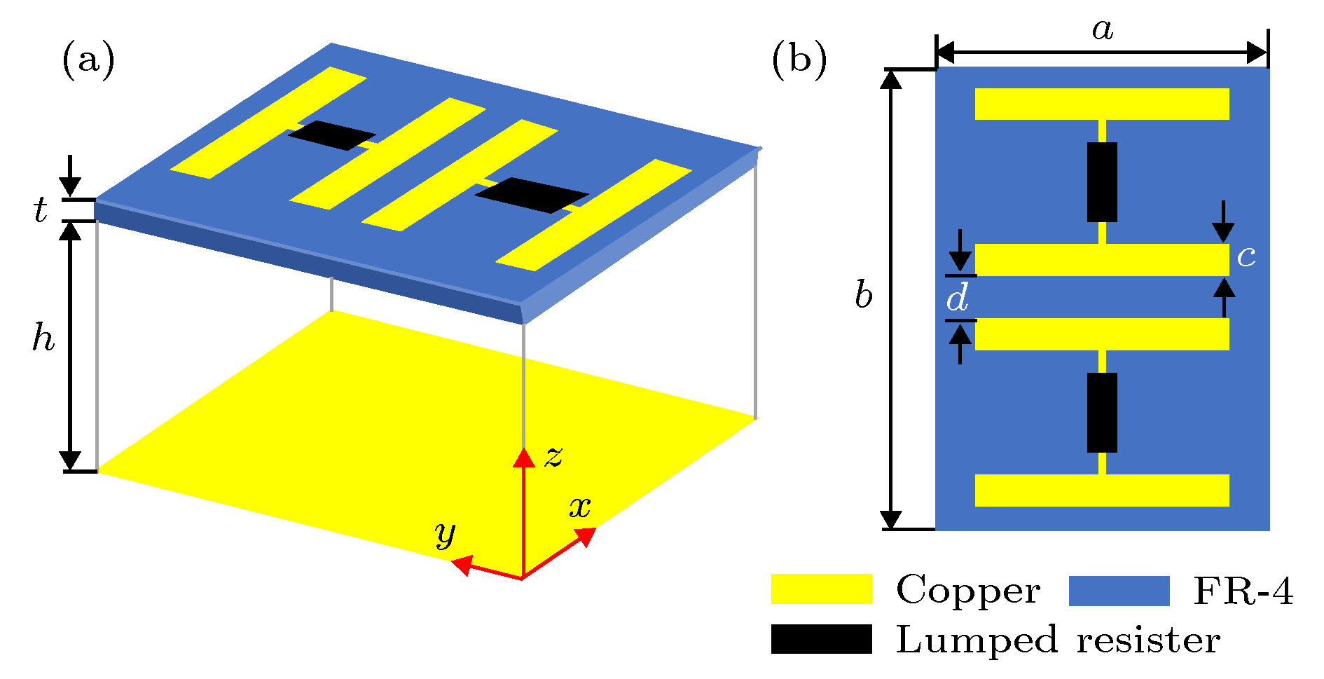
图 2 吸波体结构设计 (a) 三维视图; (b) 正视图
Fig. 2. Design of the absorber: (a) 3-D view; (b) front view.
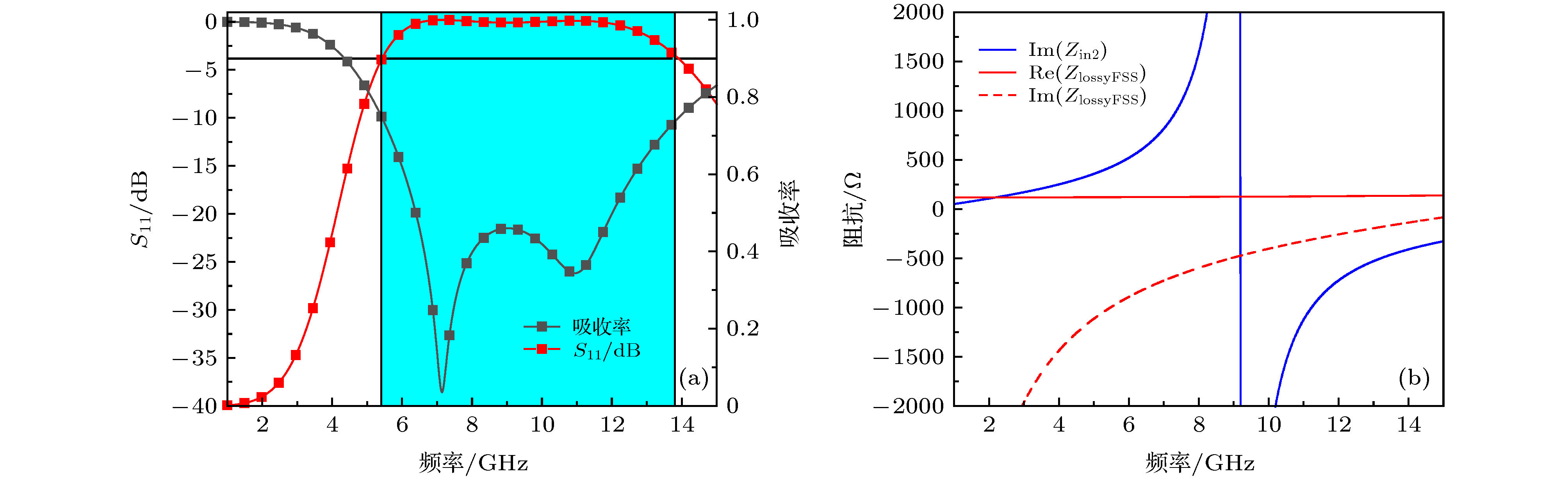
图 3 吸波体特性 (a) S11与吸收率; (b) 阻抗特性
Fig. 3. Characteristic of the absorber: (a) S11 and absorptivity; (b) impedance characteristic.
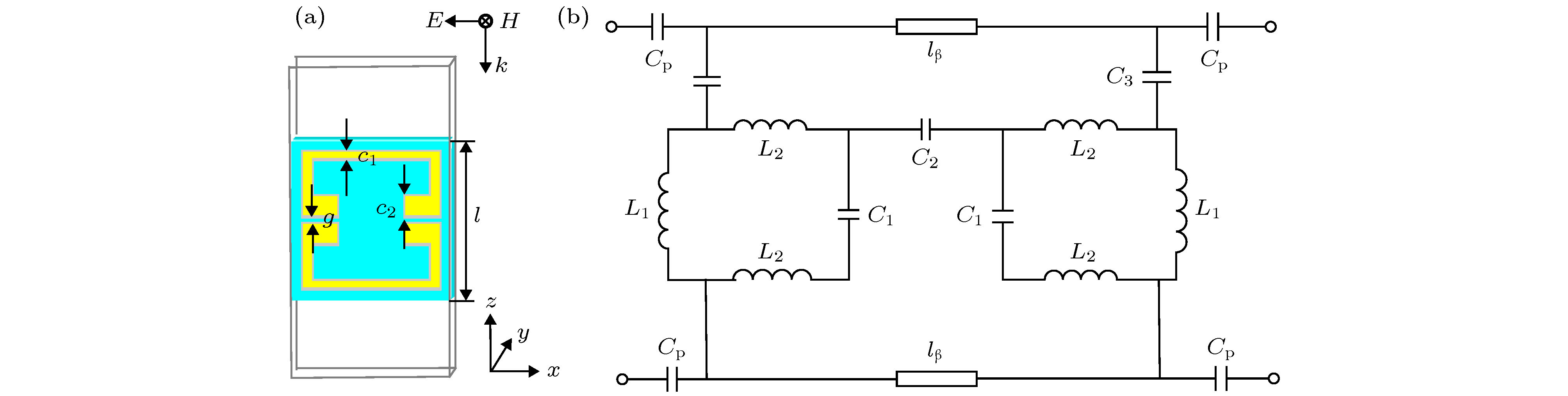
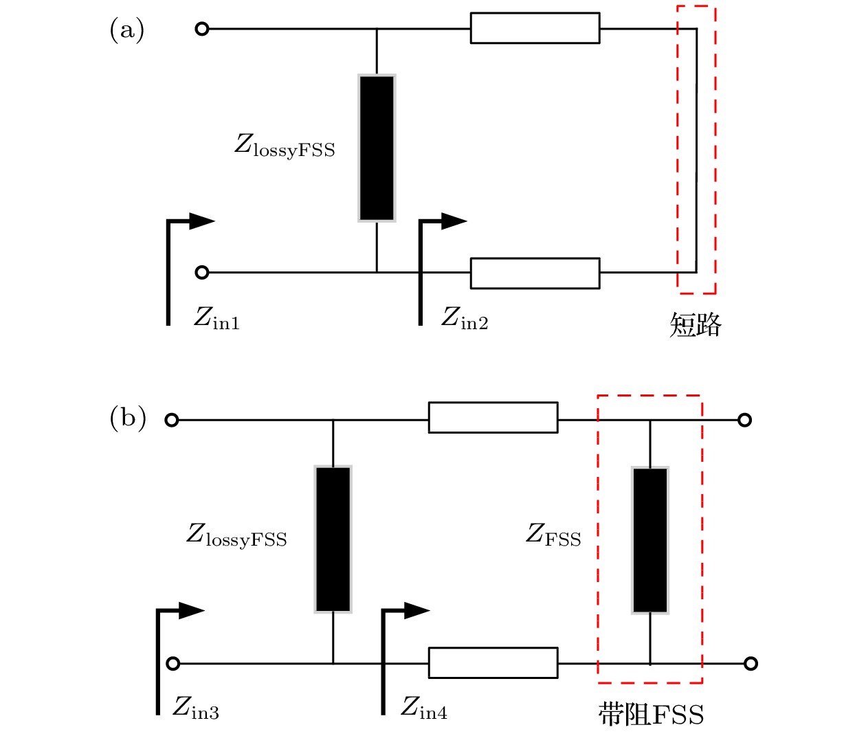
图 4 带阻FSS (a)单元设计; (b)等效电路
Fig. 4. Band-stop FSS: (a) The design of unit cell; (b) equivalent circuit.
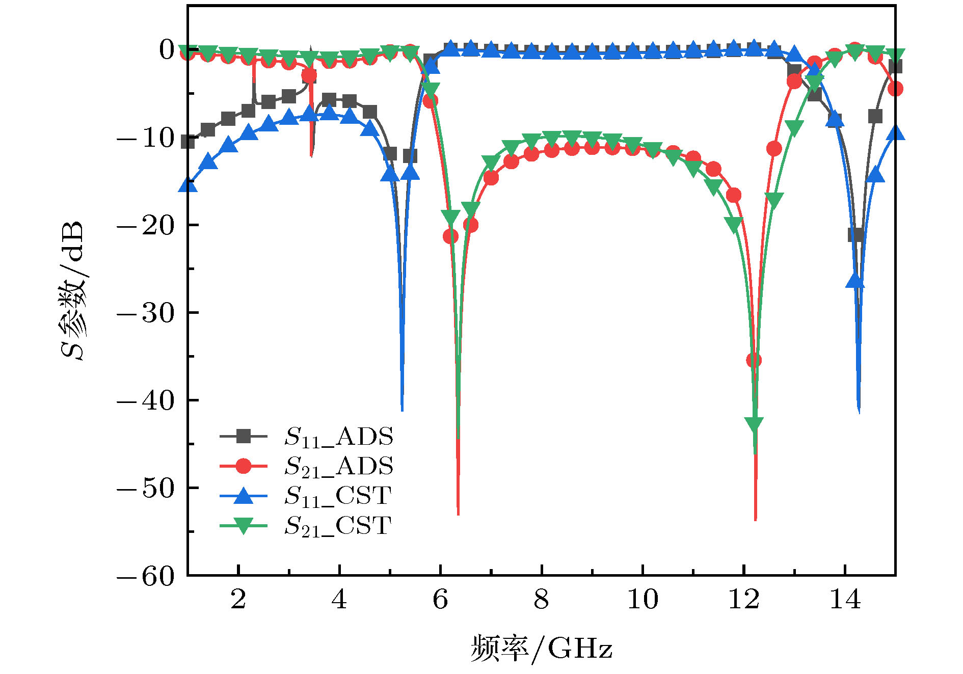
图 5 带阻FSS的等效电路仿真与全波仿真结果对比
Fig. 5. Comparison between simulation results and full wave simulation.
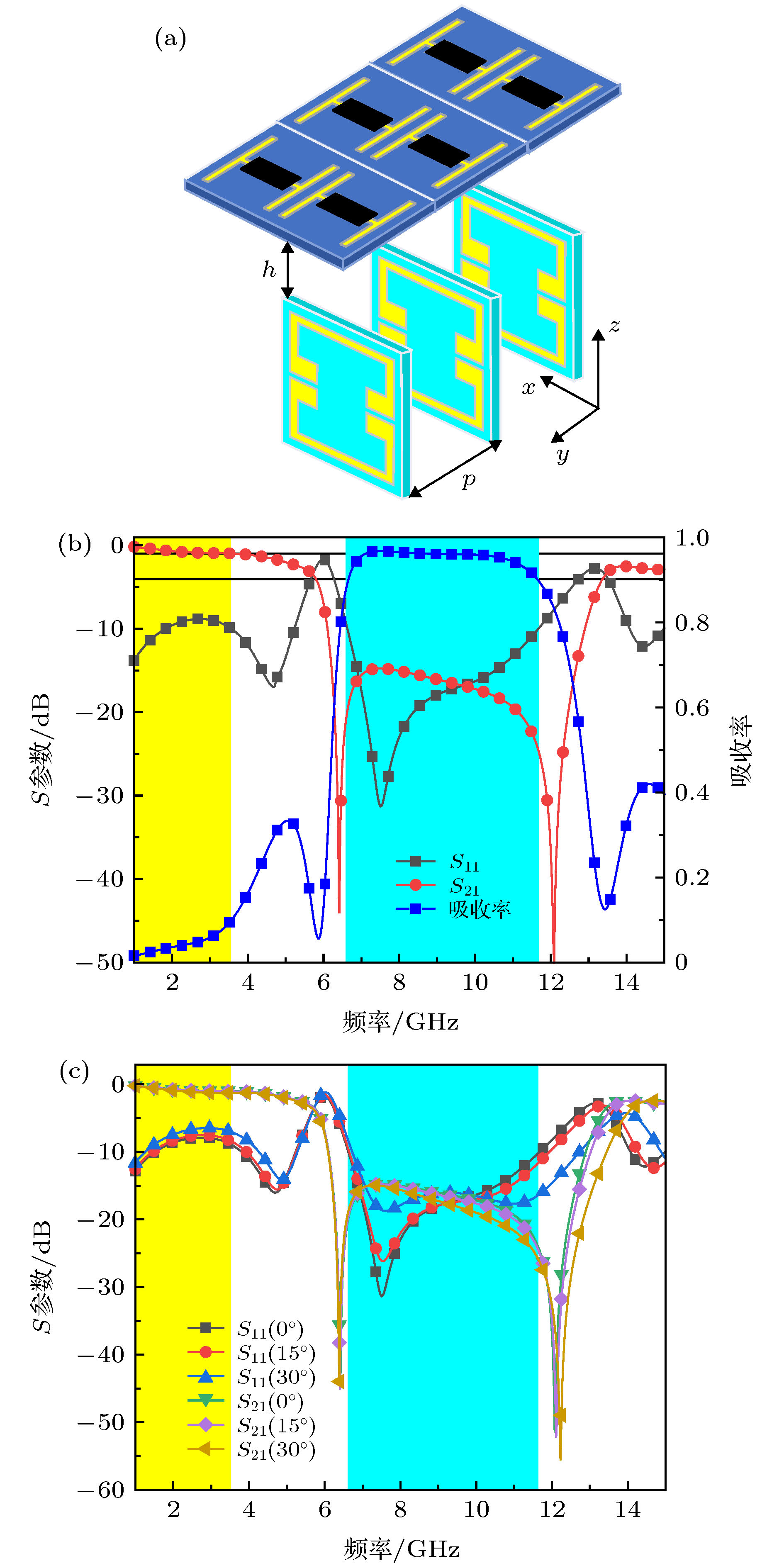
图 6 (a) AFSS的3 × 1周期结构示意图; (b)TE极化波入射下的S参数与吸收率; (c) TE极化波斜入射时的反射系数与传输系数
Fig. 6. (a) Geometry of the proposed AFSS (3 × 1 periodic structure); (b) S parameters and absorptivity at TE-polarized incidence; (c) reflection/transmission coefficients at TE-polarized oblique incidences.

图 7 AFSS样品 (a)有耗FSS; (b)带阻FSS
Fig. 7. Fabricated AFSS: (a) Lossy FSS; (b) bandstop FSS.
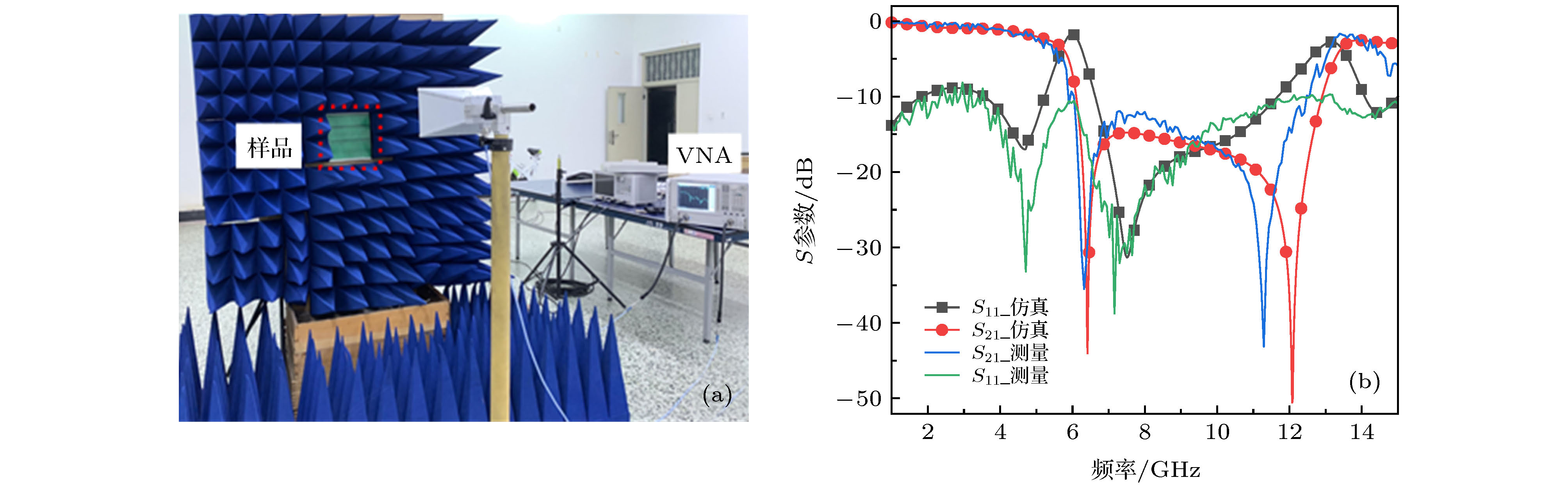
图 8 (a)实验装置(b) S参数的仿真结果与测量结果的对比
Fig. 8. (a) Experimental setup; (b) comparison between simulated and measured S parameters.
表 1 所设计AFSS与前人所设计的AFSS比较
Table 1. Comparisons between the proposed AFSS and the previous AFSSs.
 下载: 导出CSV
-
[1] Munk B A 2000 Frequency Selective Surfaces: Theory and Design (NewYork: Wiley) pp12–20.
[2] Munk B A 2009 Metamaterials: Critique and Alternatives (Hoboken: Wiley) pp50–56.
[3] Costa F, Monorchio A 2012 IEEE Trans. Antennas Propag. 60 2740
Google Scholar
[4] 周航, 屈绍波, 彭卫东, 王甲富, 马华, 张东伟, 张介秋, 柏鹏, 徐卓 2012 物理学报 61 104201
Google Scholar
Zhou H, Qu S B, Peng W D, Wang J F, Ma H, Zhang D W, Zhang J Q, Bai P, Xu Z 2012 Acta Phys. Sin. 61 104201
Google Scholar
[5] Zhong S, Wu L, Liu T, Huang J, Jiang W, Ma Y 2018 Opt. Express. 26 16466
Google Scholar
[6] Chen Q, Sang D, Guo M, Fu Y Q 2019 IEEE Trans. Antennas Propag. 67 1045
Google Scholar
[7] Wang Z F, Fu J H, Zeng Q S, Song M X, Denidni T A 2019 IEEE Trans. Antennas Propag. 18 1443
Google Scholar
[8] Guo Q X, Li Z R, Su J X, Yang L Y, Song J M 2019 IEEE Trans. Antennas Propag. 18 961
Google Scholar
[9] Chen Q, Liu L G, Chen L, Bai J J, Fu Y Q 2016 Electron. Lett. 52 418
Google Scholar
[10] Zhang Y X, Li B, Zhu L, Tang Y M, Chang Y M, Bo Y M 2018 IEEE Antennas Wirel. Propag. Lett. 17 633
Google Scholar
[11] Shen Z X, Wang J, Li B 2016 IEEE Trans. Antennas Propag. 64 3087
Google Scholar
[12] Luo G Q, Hong W, Tang H J, Chen J X, Wu K 2006 IEEE Microw. Wirel. Compon. Lett. 16 648
Google Scholar
[13] Rashid A K, Shen Z X 2010 IEEE Antennas and Propagation Society International Symposium Toronto, Canada, July 11–17, 2010 p978
[14] Yu W L, Luo G Q, Yu Y F, Liao Z, Jin H Y, Shen Z X 2019 IEEE Antennas Wirel. Propag. Lett. 18 1701
Google Scholar
[15] Yu W L, Luo G Q, Yu Y F, Cao W H, Pan Y J, Shen Z X 2019 IEEE Trans. Antennas Propag. 67 1318
Google Scholar
[16] Yu Y F, Luo G Q, Liu Q, Yu W L, Jin H Y, Liao Z, Shen Z X 2019 IEEE Access. 7 2520
Google Scholar
[17] 波扎 著 (张肇仪 译) 2010 微波工程 (北京: 电子工业出版社) 第157—160页
Pozer D M (translated by Zhang Z Y) 2010 Microwave Engineering (Beijing: Electronic Industry Press) pp157–160 (in Chinese)
[18] Costa F, Monorchio A, Manara G 2016 IEEE Electromagnetic Compatibility Magazine. 5 67
Google Scholar
[19] 周良 2011 博士学位论文 (南京: 南京航空航天大学)
Zhou L 2011 Ph. D. Dissertation (Nanjing: Nanjing University of Aeronautics and Astronautics) (in Chinese)
[20] Ghodgaonkar D K, Varadan V V, Varadan V K IEEE 1989 Trans. Instrum. Meas. 38 789
Google Scholar

 下载:
下载:
计量
- 文章访问数: 13692
- PDF下载量: 475
- 被引次数: 0
