


-
采用磁性电磁超构材料, 设计了具有柱对称梯度折射率分布的二维体系, 根据梯度的不同可以实现光束的不同调制功能. 通过等效介质理论, 可以计算磁性电磁超构材料的等效电磁参数, 从而获得等效折射率. 而且, 随着磁性柱半径的变化, 可以实现等效折射率的灵活调制. 尤为特别的是, 通过改变外加偏置磁场的空间分布, 可以实现不同的折射率梯度, 这也是磁性电磁超构材料相对于普通介质体系的优越性. 基于多重散射理论, 对光束在二维体系中的传输行为进行了模拟计算, 研究结果表明通过调制外加偏置磁场可以实现光束的囚禁、光束的内偏折和外偏折、以及分束等功能. 而且, 通过改变外加磁场可以实现不同功能间的切换, 这种灵活的调制能力为光束传输提供了新的自由度.In this work, a cylindrically symmetric gradient-refractivity two-dimensional electromagnetic system is constructed by using the magnetic metamaterials consisting of an array of ferrite rods. With the change of the bias magnetic field, the different gradient-refractivity systems can be obtained, based on which a tunable flexible beam is demonstrated. Based on the effective-medium theory, the effective electric permittivity and the effective magnetic permeability can be retrieved and thus the effective refractive index is obtained straightforwardly. It is shown that with the variation of the ferrite rod radius, an effective refractivity profile with particular gradient can be realized, which exhibits the electromagnetic “black-hole-like” effect. Especially, the gradient refractivity profile is also designed by introducing the gradient bias magnetic field, which, in principle, results in the refractivity profile with many different gradients. Finally, the propagation of a Gaussian beam in the gradient-refractivity system is simulated by using the multiple scattering theory. A few different phenomena are observed such as the “black-hole” effect, the interior beam deflection, the exterior beam deflection, and the beam splitting. Furthermore, the functionalities can be switched between each other by controlling the bias magnetic field and adding an additional degree of freedom for beam propagation.
-
Keywords:
- electromagnetic black hole /
- gradient index /
- effective-medium theory /
- multiple scattering theory
[1] Joannopoulos J D, Meade R D, Winn J N 2008 Photonic Crystals (New Jersey: Princeton University Press)
[2] Yan B, Xie J L, Liu E X, Peng Y C, Ge R, Liu J J, Wen S C 2019 Phys. Rev. Appl. 12 044004
 Google Scholar
[3] Vaidya S, Benalcazar W A, Cerjan A, Rechtsman M C 2021 Phys. Rev. Lett. 127 023605
Google Scholar
[4] Shi F L, Cao Y, Chen X D, Liu J W, Chen W J, Chen M, Dong J W 2021 Phys. Rev. Appl. 15 024002
Google Scholar
[5] Xie B Y, Su G X, Wang H F, Liu F, Hu L M, Yu S Y, Zhan P, Lu M H, Wang Z L, Chen Y F 2020 Nat. Commun. 11 3768
Google Scholar
[6] Cai W S, Shalaev V 2010 Optical Metamaterials: Fundamentals and Applications (New York: Springer)
[7] Yu N F, Genevet P, Kats M A, Aieta F, Tetienne J P, Capasso F, Gaburro Z 2011 Science 334 333
Google Scholar
[8] Sun S L, He Q, Xiao S Y, Xu Q, Li X, Zhou L 2012 Nat. Mater. 11 426
Google Scholar
[9] Chen H T, Taylor A J, Yu N F 2016 Rep. Prog. Phys. 79 076401
Google Scholar
[10] Li L, Liu Z X, Ren X F, Wang S M, Su V, Chen M K, Chu C H, Kuo H Y, Liu B H, Zang W B, Guo G C, Zhang L J, Wang Z L, Zhu S N, Tsai D P 2020 Science 368 1487
Google Scholar
[11] Nikolov D K, Bauer A, Cheng F, Kato H, Vamivakas A N, Rolland J P 2021 Sci. Adv. 7 eabe5112
Google Scholar
[12] Leonhardt U 2006 Science 312 1777
Google Scholar
[13] Pendry J B, Schurig D, Smith D R 2006 Science 312 1780
Google Scholar
[14] Lai Y, Ng J, Chen H Y, Zhang Z Q, Chan C T 2010 Front. Phys. China 5 308
Google Scholar
[15] Xu L, Chen H Y 2015 Nat. Photonics 9 15
Google Scholar
[16] McCall M, Pendry J B, Galdi V, et al. 2018 J. Opt. 20 063001
Google Scholar
[17] Chen H Y, Chan C T 2010 J. Phys. D: Appl. Phys. 43 113001
Google Scholar
[18] Zhu J, Liu Y Q, Liang Z X, Chen T N, Li J S 2018 Phys. Rev. Lett. 121 234301
Google Scholar
[19] Schittny R, Kadic M, Guenneau S, Wegener M 2013 Phys. Rev. Lett. 110 195901
Google Scholar
[20] Zhang S, Genov D A, Sun C, Zhang X 2008 Phys. Rev. Lett. 100 123002
Google Scholar
[21] Elyasi M, Bhatia C S, Qiu C W, Yang H 2016 Phys. Rev. B 93 104418
Google Scholar
[22] Yang F, Mei Z L, Jin T Y, Cui T J 2012 Phys. Rev. Lett. 109 053902
Google Scholar
[23] Magnus F, Wood B, Moore J, Morrison K, Perkings G, Fyson J, Wiltshire M C K, Caplin D, Cohen L F, Pendry J B 2008 Nat. Mater. 7 295
Google Scholar
[24] Xu Y D, Fu Y Y, Chen H Y 2016 Nat. Rev. Mater. 1 16067
Google Scholar
[25] Xu L, Chen H Y, Tyc T, Xie Y B, Cummer S A 2016 Phys. Rev. B 93 041406
Google Scholar
[26] Xu L, Ge H, Li J S, He R Q, Zhou J J, Zhu S N, Liu H, Chen H Y, 2020 Phys. Rev. Appl. 13 054007
Google Scholar
[27] Ma Y G, Ong C K, Tyc T, Leonhardt U 2009 Nat. Mater. 8 639
Google Scholar
[28] Smolyaninova V N, Smolyaninov I I, Kildishev A V, Shalaev V 2010 Opt. Lett. 35 3396
Google Scholar
[29] Zentgraf T, Liu Y M, Mikkelsen M H, Valentine J, Zhang X 2011 Nat. Nanotechnol. 6 151
Google Scholar
[30] Bitton O, Bruch R, Leonhardt U 2018 Phys. Rev. Appl. 10 044059
Google Scholar
[31] Zhang Y, He Y, Wang H W, Sun L, Su Y K 2021 ACS Photonics 8 202
[32] Genov D A, Zhang S, Zhang X 2009 Nat. Phys. 5 687
Google Scholar
[33] Torres T, Patrick S, Coutant A, Richartz M, Tedford E W, Weinfurtner S 2017 Nat. Phys. 13 833
Google Scholar
[34] Roldán-Molina A, Nunez A S, Duine R A 2017 Phys. Rev. Lett. 118 061301
Google Scholar
[35] Mi Y Z, Zhai W, Cheng L, Xi C Y, Yu X 2021 Appl. Phys. Lett. 118 114101
Google Scholar
[36] Liu S Y, Chen W K, Du J J, Lin Z F, Chui S T, Chan C T 2008 Phys. Rev. Lett. 101 157407
Google Scholar
[37] Yu X N, Chen H J, Lin H X, Zhou J L, Yu J J, Qian C X, Liu S Y 2014 Opt. Lett. 39 4643
Google Scholar
[38] 林海笑, 俞昕宁, 刘士阳 2015 物理学报 64 034203
Google Scholar
Lin H X, Yu X N, Liu S Y 2015 Acta Phys. Sin. 64 034203
Google Scholar
[39] Pozar D M 2005 Microwave Engineering (3rd Ed.) (New York: Wiley)
[40] Jin J F, Liu S Y, Lin Z F, Chui S T 2011 Phys. Rev. B 84 115101
Google Scholar
[41] Centeno E, Cassagne D, Albert J P 2006 Phys. Rev. B 73 235119
Google Scholar
[42] Kurt H, Citrin D S 2007 Opt. Express 15 1240
Google Scholar
[43] Wu Q, Gibbons J M, Park W 2008 Opt. Express 16 16941
Google Scholar
[44] Vasic B, Isic G, Gajic R, Hingerl K 2010 Opt. Express 18 20321
Google Scholar
[45] Liu S Y, Li L, Lin Z F, Chen H Y, Zi J, Chan C T 2010 Phys. Rev. B 82 054204
Google Scholar
[46] Felbacq D, Tayeb G, Maystre D 1994 J. Opt. Soc. Am. A 11 2526
Google Scholar
[47] Liu S Y, Lin Z F 2006 Phys. Rev. E 73 066609
Google Scholar
[48] Chen S W, Du J J, Liu S Y, Lin Z F, Chui S T 2008 Opt. Lett. 33 2476
Google Scholar
[49] Chen S W, Du J J, Liu S Y, Lin Z F, Chui S T 2008 Phys. Rev. A 78 043803
Google Scholar
[50] Chen J F, Liang W Y, Li Z Y 2020 Phys. Rev. B 101 214102
Google Scholar
[51] Poo Y, Wu R X, Liu S Y, Yang Y, Lin Z F, Chui S T 2012 Appl. Phys. Lett. 101 081912
Google Scholar
[52] Xu Y D, Gu C D, Hou B, Lai Y, Li J S, Chen H Y 2013 Nat. Commun. 4 2561
Google Scholar
[53] Wu H B, Xi X, Li X M, Poo Y, Liu S Y, Wu R X 2022 Photonics Res. 10 610
Google Scholar
[54] Luo Q L, Zhao L Z, Zhou J L, Zhang L, Wen G F, Ba Q T, Wu H B, Lin Z F, Liu S Y 2022 Front. Mater. 9 845344
Google Scholar
-
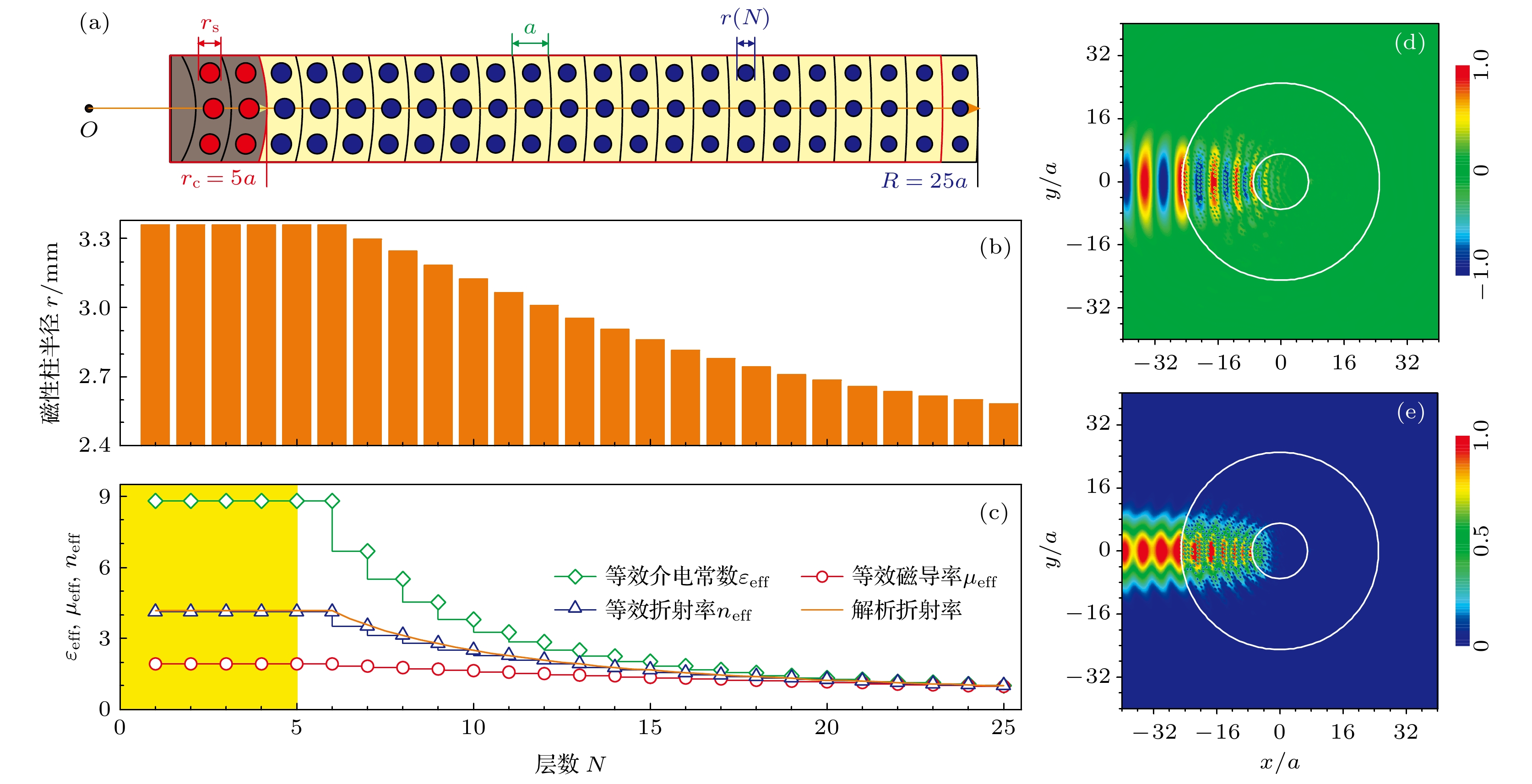
图 1 通过改变结构中的半径分布来实现折射率梯度指数
$\eta = 2$ 的体系 (a) 结构示意图显示该体系包括 25 层, 每层的厚度$a = 12{\text{ }}{\rm{mm}}$ , 内核吸收体半径${r_{\rm{c}}} = 5 a$ , 体系的半径$ R = 25 a $ , 磁性柱的相对介电常数${\varepsilon _{\rm{s}}} = 25$ ; (b) 不同壳层中的磁性柱半径和 (c) 相应的等效介电常数${\varepsilon _{{\rm{eff}}}}$ 、等效磁导率${\mu _{{\rm{eff}}}}$ 及由此得到的等效折射率${n_{{\rm{eff}}}}$ ; 高斯光束入射到该体系的(d)电场分布和(e)强度分布. 施于体系的外加偏置磁场${H_0} = 480{\text{ }}{\rm{Oe}}$ , 工作频率为$f = 2.7$ GHz. 白色圆形标记出体系的边界和内核吸收体的边缘位置Fig. 1. The system with gradient index
$\eta = 2$ are implemented by varying the rod radius: (a) Schematic diagram presents the system made up of 25 concentric layers with the layer thickness$a = 12{\text{ }}\rm mm$ , the radius of the absorbing core part${r_{\rm{c}}} = 5 a$ , the radius of the system$ R = 25 a $ , and the relative permittivity of the ferrite rod${\varepsilon _{\rm{s}}} = 25$ ; (b) ferrite rod radius as well as (c) the effective permittivity${\varepsilon _{{\rm{eff}}}}$ , permeability${\mu _{{\rm{eff}}}}$ , and the corresponding effective index${n_{{\rm{eff}}}}$ are plotted as the functions of the number of the layer; (d) electric field pattern and (e) corresponding intensity pattern are simulated for the on-center incidence of a Gaussian beam on the system. The bias magnetic field is${H_0} = 480{\text{ }}{\rm{Oe}}$ and the operating frequency is$f = 2.7$ GHz. Two white circles denote the boundaries of the system and the absorbing core part, respectively.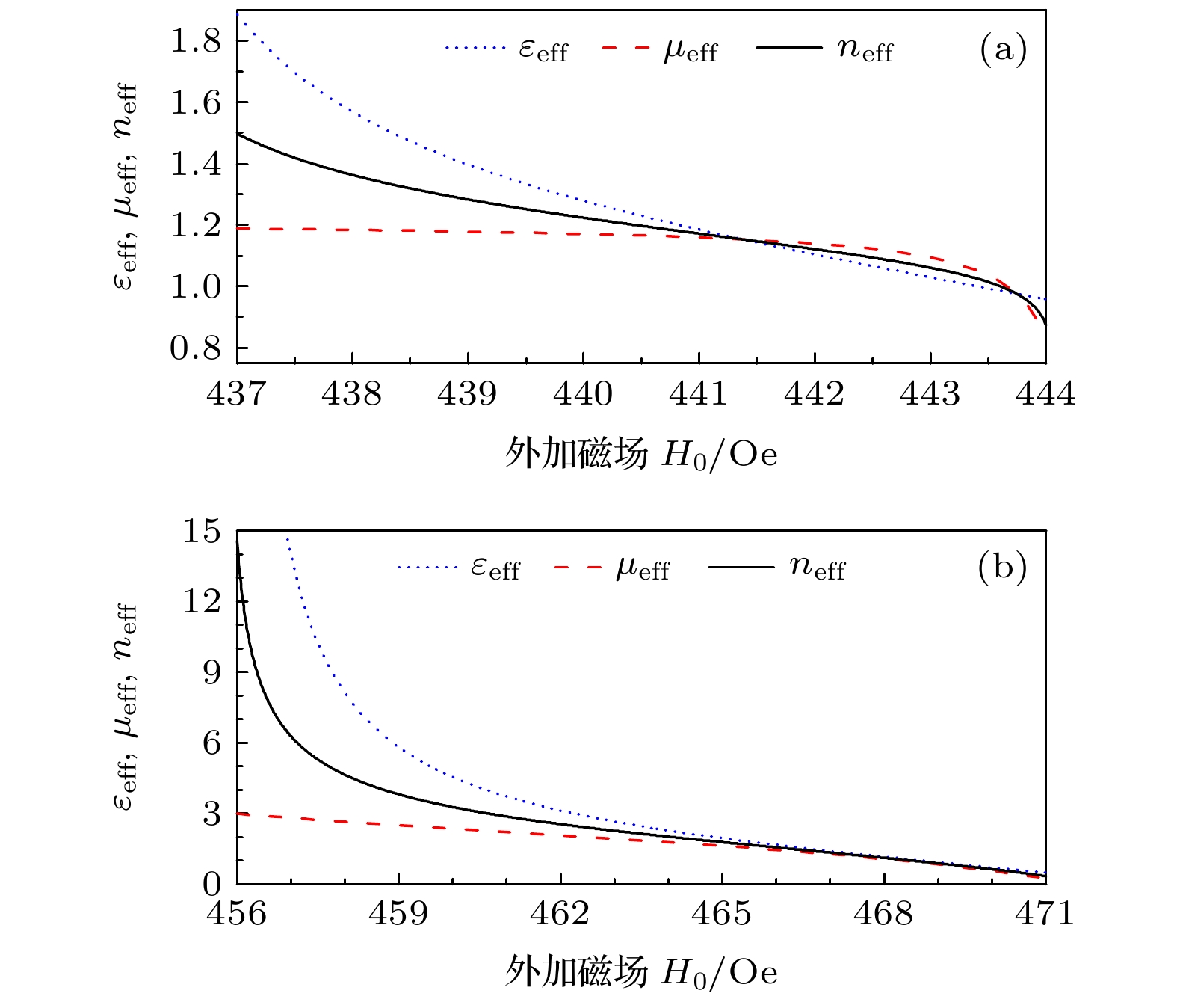
图 2 采用等效介质理论计算
${\varepsilon _{{\rm{eff}}}}$ 、${\mu _{{\rm{eff}}}}$ 以及${n_{{\rm{eff}}}}$ 随外加偏置磁场${H_0}$ 的变化. 把磁性电磁超构材料看成是正方晶格, 晶格常数为$a = 12{\text{ }}{\rm{mm}}$ , 考察了两种不同磁性柱大小的情形 (a) 磁性柱半径为$r_{\rm{s}}' = 0.12 a$ ; (b) 磁性柱半径为${r_{\rm{s}}} = 0.35 a$ . 工作频率为$f = 2.7$ GHzFig. 2. The effective permittivity
${\varepsilon _{{\rm{eff}}}}$ , permeability${\mu _{{\rm{eff}}}}$ , and the corresponding effective index${n_{{\rm{eff}}}}$ retrieved with the effective-medium theory are plotted as the functions of the bias magnetic field${H_0}$ . The magnetic metamaterial is considered as a square lattice with lattice separation$a = 12{\text{ }}{\rm{mm}}$ and two different rod radii with (a)$r_{\rm{s}}' = 0.12 a$ and (b)${r_{\rm{s}}} = 0.35 a$ are investigated. The operating frequency is$f = 2.7$ GHz.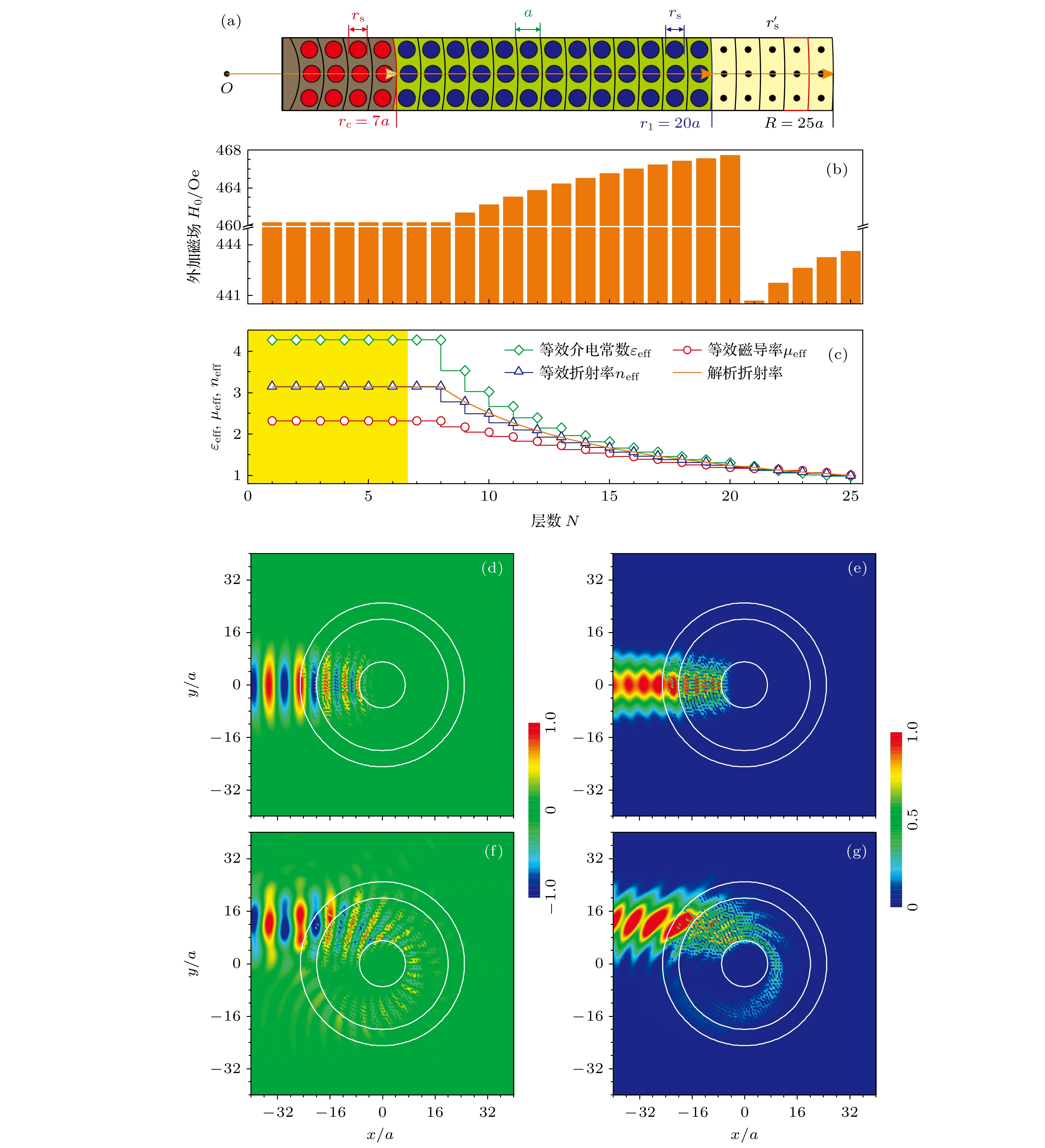
图 3 通过改变空间中的外加偏置磁场
${H_0}$ 分布实现折射率梯度指数$\eta = 2$ 的体系 (a) 结构示意图显示该体系包括 25 层, 每层的厚度$a = 12{\text{ }}{\rm{mm}}$ , 内核吸收体半径$r_{\rm{c}}' = 7 a$ , 折射率梯度区域的内壳层半径为$ {r_1} = 20 a $ , 体系的半径$ R = 25 a $ ; (b) 不同壳层中的外加磁场${H_0}$ 的分布; (c) 相应的${\varepsilon_{{\rm{eff}}}}$ ,${\mu_{{\rm{eff}}}}$ 及${n_{\rm eff}}$ . 高斯光束对心入射到该体系的(d)电场分布, (e)强度分布以及偏心入射的(f)电场分布和(g)强度分布. 内部区域和外部区域的磁性柱半径分别为${r_{\rm{s}}} = 0.35 a$ ,$r_{\rm{s}}' = 0.12 a$ , 工作频率为$f = 2.7$ GHz, 白色圆形标记出体系不同区域的位置Fig. 3. The system with gradient index
$\eta = 2$ are implemented by varying the distribution of bias magnetic field${H_0}$ : (a) Schematic diagram presents the system made up of 25 concentric layers with the layer thickness$a = 12{\text{ }}{\rm{mm}}$ , the radius of the absorbing core part$r_{\rm{c}}' = 7 a$ , the inner radius of the gradient index area is$ {r_1} = 20 a $ , and the radius of the system$ R = 25 a $ ; (b) the bias magnetic field${H_0}$ ; (c)${\varepsilon_{{\rm{eff}}}}$ ,${\mu_{{\rm{eff}}}}$ ,${n_{\rm eff}}$ . The electric field patterns and the corresponding intensity patterns are simulated for the on-center ((d), (e)) and off-center ((f), (g)) incidence of a Gaussian beam on the system to illustrate the electromagnetic “black hole” effect. The ferrite rod radii are${r_{\rm{s}}} = 0.35 a$ and$r_{\rm{s}}' = 0.12 a$ for the inner and outer areas, respectively, and the operating frequency is$f = 2.7$ GHz. Three white circles denote the boundaries of different areas in the system.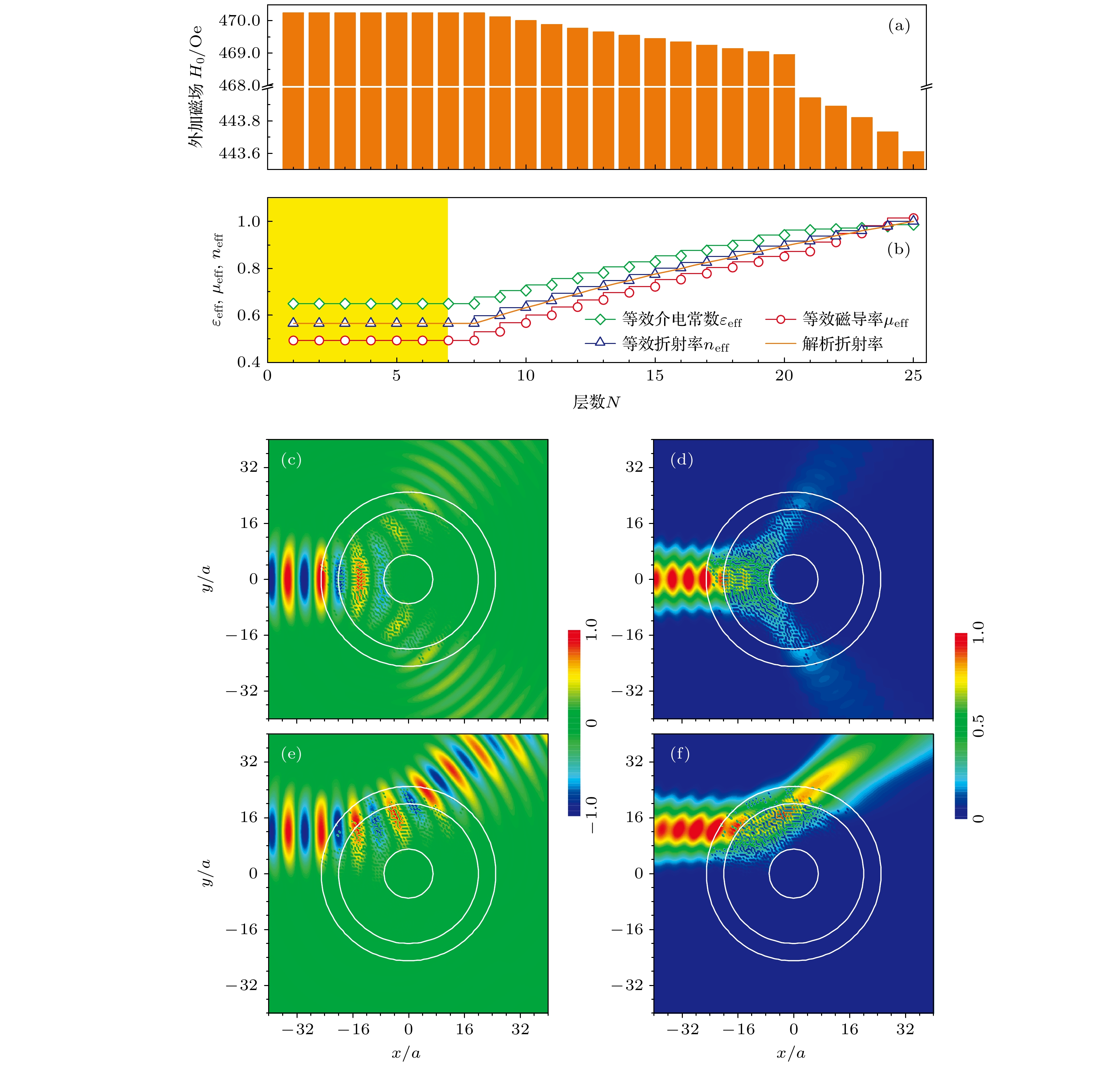
图 4 通过改变空间中的外加偏置磁场
${H_0}$ 分布实现折射率梯度指数$\eta = - 1$ 的体系, 体系结构与图 3 相同 (a)外加偏置磁场${H_0}$ 的分布; (b)${\varepsilon _{{\rm{eff}}}}$ ,${\mu _{{\rm{eff}}}}$ ,${n_{{\rm{eff}}}}$ 分布. 高斯光束对心入射到该体系的(c)电场分布, (d)强度分布, 以及偏心入射的(e)电场分布, (f)强度分布. 内部区域和外部区域的磁性柱半径分别为${r_{\text{s}}} = 0.35 a$ 和$r_{\rm{s}}' = 0.12 a$ , 工作频率为$f = 2.7$ GHz. 白色圆形标记出体系不同区域的位置Fig. 4. The system with gradient index
$\eta = - 1$ are implemented by varying the distribution of bias magnetic field${H_0}$ . The schematic diagram is the same as that in Fig. 3: (a) The distribution of bias magnetic field; (b)${\varepsilon _{{\rm{eff}}}}$ ,${\mu _{{\rm{eff}}}}$ ,${n_{{\rm{eff}}}}$ . The electric field patterns and the corresponding intensity patterns are simulated for the on-center ((c), (d)) and off-center ((e), (f)) incidence of a Gaussian beam on the system. The ferrite rod radii are${r_{\rm{s}}} = 0.35 a$ and$r_{\rm{s}}' = 0.12 a$ for the inner and outer areas, respectively, and the operating frequency is$f = 2.7$ GHz. Three white circles denote the boundaries of different areas in the system.
图 5 通过改变空间中的外加偏置磁场
${H_0}$ 分布来实现折射率梯度指数$\eta = 1$ 的体系. 体系结构与图 3 相同 (a)外加偏置磁场${H_0}$ 的分布; (b)${\varepsilon _{{\rm{eff}}}}$ ,${\mu _{{\rm{eff}}}}$ ${n_{{\rm{eff}}}}$ . 高斯光束对心入射到该体系的(c)电场分布和(d)强度分布, 以及偏心入射的(e)电场分布和(f)强度分布. 内部区域和外部区域的磁性柱半径分别为${r_{\rm{s}}} = 0.35 a$ 和$r_{\rm{s}}' = 0.12 a$ , 工作频率为$f = 2.7$ GHz. 白色圆形标记出体系不同区域的位置Fig. 5. The system with gradient index
$\eta = 1$ are implemented by varying the distribution of bias magnetic field${H_0}$ . The schematic diagram is the same as that in Fig.3: (a) The distribution of bias magnetic field; (b)${\varepsilon _{{\rm{eff}}}}$ ,${\mu _{{\rm{eff}}}}$ ,${n_{{\rm{eff}}}}$ . The electric field patterns and the corresponding intensity patterns are simulated for the on-center ((c), (d)) and off-center ((e), (f)) incidence of a Gaussian beam on the system. The ferrite rod radii are${r_{\rm{s}}} = 0.35 a$ and$r_{\rm{s}}' = 0.12 a$ for the inner and outer areas, respectively, and the operating frequency is$f = 2.7$ GHz. Three white circles denote the boundaries of different areas in the system.
图 6 通过改变空间中的外加偏置磁场
${H_0}$ 分布实现折射率梯度指数$\eta = 3$ 的体系, 体系结构与图 3 相同 (a)外加偏置磁场${H_0}$ 分布; (b)${\varepsilon _{{\rm{eff}}}}$ ,${\mu _{{\rm{eff}}}}$ ,${n_{{\rm{eff}}}}$ . 高斯光束对心入射到该体系的(c)电场分布, (d)强度分布, 以及偏心入射的(e)电场分布, (f)强度分布. 内部区域和外部区域的磁性柱半径分别为${r_{\rm{s}}} = 0.35 a$ 和$r_{\rm{s}}' = 0.12 a$ , 工作频率为$f = 2.7$ GHz. 白色圆形标记出体系不同区域的位置Fig. 6. The system with gradient index
$\eta = 3$ are implemented by varying the distribution of bias magnetic field${H_0}$ . The schematic diagram is the same as that in Fig. 3: (a) The distribution of bias magnetic field; (b)${\varepsilon _{{\rm{eff}}}}$ ,${\mu _{{\rm{eff}}}}$ ,${n_{{\rm{eff}}}}$ . The electric field patterns and the corresponding intensity patterns are simulated for the on-center ((c), (d)) and off-center ((e), (f)) incidence of a Gaussian beam on the system. The ferrite rod radii are${r_{\rm{s}}} = 0.35 a$ and$r_{\rm{s}}' = 0.12 a$ for the inner and outer areas, respectively, and the operating frequency is$f = 2.7$ GHz. Three white circles denote the boundaries of different areas in the system. -
[1] Joannopoulos J D, Meade R D, Winn J N 2008 Photonic Crystals (New Jersey: Princeton University Press)
[2] Yan B, Xie J L, Liu E X, Peng Y C, Ge R, Liu J J, Wen S C 2019 Phys. Rev. Appl. 12 044004
Google Scholar
[3] Vaidya S, Benalcazar W A, Cerjan A, Rechtsman M C 2021 Phys. Rev. Lett. 127 023605
Google Scholar
[4] Shi F L, Cao Y, Chen X D, Liu J W, Chen W J, Chen M, Dong J W 2021 Phys. Rev. Appl. 15 024002
Google Scholar
[5] Xie B Y, Su G X, Wang H F, Liu F, Hu L M, Yu S Y, Zhan P, Lu M H, Wang Z L, Chen Y F 2020 Nat. Commun. 11 3768
Google Scholar
[6] Cai W S, Shalaev V 2010 Optical Metamaterials: Fundamentals and Applications (New York: Springer)
[7] Yu N F, Genevet P, Kats M A, Aieta F, Tetienne J P, Capasso F, Gaburro Z 2011 Science 334 333
Google Scholar
[8] Sun S L, He Q, Xiao S Y, Xu Q, Li X, Zhou L 2012 Nat. Mater. 11 426
Google Scholar
[9] Chen H T, Taylor A J, Yu N F 2016 Rep. Prog. Phys. 79 076401
Google Scholar
[10] Li L, Liu Z X, Ren X F, Wang S M, Su V, Chen M K, Chu C H, Kuo H Y, Liu B H, Zang W B, Guo G C, Zhang L J, Wang Z L, Zhu S N, Tsai D P 2020 Science 368 1487
Google Scholar
[11] Nikolov D K, Bauer A, Cheng F, Kato H, Vamivakas A N, Rolland J P 2021 Sci. Adv. 7 eabe5112
Google Scholar
[12] Leonhardt U 2006 Science 312 1777
Google Scholar
[13] Pendry J B, Schurig D, Smith D R 2006 Science 312 1780
Google Scholar
[14] Lai Y, Ng J, Chen H Y, Zhang Z Q, Chan C T 2010 Front. Phys. China 5 308
Google Scholar
[15] Xu L, Chen H Y 2015 Nat. Photonics 9 15
Google Scholar
[16] McCall M, Pendry J B, Galdi V, et al. 2018 J. Opt. 20 063001
Google Scholar
[17] Chen H Y, Chan C T 2010 J. Phys. D: Appl. Phys. 43 113001
Google Scholar
[18] Zhu J, Liu Y Q, Liang Z X, Chen T N, Li J S 2018 Phys. Rev. Lett. 121 234301
Google Scholar
[19] Schittny R, Kadic M, Guenneau S, Wegener M 2013 Phys. Rev. Lett. 110 195901
Google Scholar
[20] Zhang S, Genov D A, Sun C, Zhang X 2008 Phys. Rev. Lett. 100 123002
Google Scholar
[21] Elyasi M, Bhatia C S, Qiu C W, Yang H 2016 Phys. Rev. B 93 104418
Google Scholar
[22] Yang F, Mei Z L, Jin T Y, Cui T J 2012 Phys. Rev. Lett. 109 053902
Google Scholar
[23] Magnus F, Wood B, Moore J, Morrison K, Perkings G, Fyson J, Wiltshire M C K, Caplin D, Cohen L F, Pendry J B 2008 Nat. Mater. 7 295
Google Scholar
[24] Xu Y D, Fu Y Y, Chen H Y 2016 Nat. Rev. Mater. 1 16067
Google Scholar
[25] Xu L, Chen H Y, Tyc T, Xie Y B, Cummer S A 2016 Phys. Rev. B 93 041406
Google Scholar
[26] Xu L, Ge H, Li J S, He R Q, Zhou J J, Zhu S N, Liu H, Chen H Y, 2020 Phys. Rev. Appl. 13 054007
Google Scholar
[27] Ma Y G, Ong C K, Tyc T, Leonhardt U 2009 Nat. Mater. 8 639
Google Scholar
[28] Smolyaninova V N, Smolyaninov I I, Kildishev A V, Shalaev V 2010 Opt. Lett. 35 3396
Google Scholar
[29] Zentgraf T, Liu Y M, Mikkelsen M H, Valentine J, Zhang X 2011 Nat. Nanotechnol. 6 151
Google Scholar
[30] Bitton O, Bruch R, Leonhardt U 2018 Phys. Rev. Appl. 10 044059
Google Scholar
[31] Zhang Y, He Y, Wang H W, Sun L, Su Y K 2021 ACS Photonics 8 202
[32] Genov D A, Zhang S, Zhang X 2009 Nat. Phys. 5 687
Google Scholar
[33] Torres T, Patrick S, Coutant A, Richartz M, Tedford E W, Weinfurtner S 2017 Nat. Phys. 13 833
Google Scholar
[34] Roldán-Molina A, Nunez A S, Duine R A 2017 Phys. Rev. Lett. 118 061301
Google Scholar
[35] Mi Y Z, Zhai W, Cheng L, Xi C Y, Yu X 2021 Appl. Phys. Lett. 118 114101
Google Scholar
[36] Liu S Y, Chen W K, Du J J, Lin Z F, Chui S T, Chan C T 2008 Phys. Rev. Lett. 101 157407
Google Scholar
[37] Yu X N, Chen H J, Lin H X, Zhou J L, Yu J J, Qian C X, Liu S Y 2014 Opt. Lett. 39 4643
Google Scholar
[38] 林海笑, 俞昕宁, 刘士阳 2015 物理学报 64 034203
Google Scholar
Lin H X, Yu X N, Liu S Y 2015 Acta Phys. Sin. 64 034203
Google Scholar
[39] Pozar D M 2005 Microwave Engineering (3rd Ed.) (New York: Wiley)
[40] Jin J F, Liu S Y, Lin Z F, Chui S T 2011 Phys. Rev. B 84 115101
Google Scholar
[41] Centeno E, Cassagne D, Albert J P 2006 Phys. Rev. B 73 235119
Google Scholar
[42] Kurt H, Citrin D S 2007 Opt. Express 15 1240
Google Scholar
[43] Wu Q, Gibbons J M, Park W 2008 Opt. Express 16 16941
Google Scholar
[44] Vasic B, Isic G, Gajic R, Hingerl K 2010 Opt. Express 18 20321
Google Scholar
[45] Liu S Y, Li L, Lin Z F, Chen H Y, Zi J, Chan C T 2010 Phys. Rev. B 82 054204
Google Scholar
[46] Felbacq D, Tayeb G, Maystre D 1994 J. Opt. Soc. Am. A 11 2526
Google Scholar
[47] Liu S Y, Lin Z F 2006 Phys. Rev. E 73 066609
Google Scholar
[48] Chen S W, Du J J, Liu S Y, Lin Z F, Chui S T 2008 Opt. Lett. 33 2476
Google Scholar
[49] Chen S W, Du J J, Liu S Y, Lin Z F, Chui S T 2008 Phys. Rev. A 78 043803
Google Scholar
[50] Chen J F, Liang W Y, Li Z Y 2020 Phys. Rev. B 101 214102
Google Scholar
[51] Poo Y, Wu R X, Liu S Y, Yang Y, Lin Z F, Chui S T 2012 Appl. Phys. Lett. 101 081912
Google Scholar
[52] Xu Y D, Gu C D, Hou B, Lai Y, Li J S, Chen H Y 2013 Nat. Commun. 4 2561
Google Scholar
[53] Wu H B, Xi X, Li X M, Poo Y, Liu S Y, Wu R X 2022 Photonics Res. 10 610
Google Scholar
[54] Luo Q L, Zhao L Z, Zhou J L, Zhang L, Wen G F, Ba Q T, Wu H B, Lin Z F, Liu S Y 2022 Front. Mater. 9 845344
Google Scholar


 下载:
下载:


计量
- 文章访问数: 6993
- PDF下载量: 103
- 被引次数: 0
