


-
In the electromagnetic wave radiated by radome, there often occur pointing angle deviation, beam distortion and other phenomena, due to the complex electromagnetic medium composition, special contour and complex working environments. For conventional optimization methods, harsh and complex situations increase its workload, especially in the case that the specific location parameter information is unknown. In this paper, a method with time-inversion technique for correcting the radiation beam distortion of the complex radome is proposed. With the time-inversionl method, the concrete parameters of different positions for the radome and the surrounding environment information are not necessary to be determined in advance. The derivation shows that the environmental information is eliminated adaptively by the conjugate convolution operation, and it is proved by numerical operation that the signal of maximum radiation gain in target angle is time-inversion signal. Then based on the adaptive focusing properties of time-inversion electromagnetic waves, a top wedge radome and an icing working radome are taken as the case study. The equal amplitude phase shifting serves as the control group to highlight the advantages of time-reversal. In the end, the results show that the radiation beam pointing error can be reduced from ±10° to ±0.9° within ±45° scanning range for the top wedge radome in C-band. And the annihilated main beam can be converged again for the radome in the icing state. In addition, all the improvements are in a broadband range, and the robustness of the entire radome system is enhanced by increasing target angle energy caused by the increasing the directionality of the array radiation and the narrowing the 3 dB beamwidth. This paper provides an effective method of analyzing the complex radomes and radio wave propagations in complex media.
-
Keywords:
- time reversal /
- radome /
- beam distortion /
- aiming error
[1] 张强 2014 天线罩理论与设计方法 (北京: 国防工业出版社) 第3, 4页
Zhang Q 2014 Radome Theory and Design Methods (Vol. 1) (Beijing: National Defense Industry Press) pp3, 4 (in Chinese)
[2] 刘晓春 2017 雷达天线罩电性能设计技术 (北京: 航空工业出版社) 第1页
Liu X C 2017 Radome Electrical Performance Design Technology (Vol. 1) (Beijing: Aviation Industry Press) p1 (in Chinese)
[3] Cady W M, Karelity M B, Turner Lous A 1948 Radar Scanners and Radomes (Vol. 26, Chapter. 13) (New York: MicGraw-Hill Book Company)
[4] Kay A L 1965 IEEE Trans. Antennas Propag. 13 188
 Google Scholar
[5] 张强 2014 天线罩理论与设计方法 (北京: 国防工业出版社) 第51—59页
Zhang Q 2014 Radome Theory and Design Methods (Vol. 1) (Beijing: National Defense Industry Press) pp51–59 (in Chinese)
[6] [7] Paris D 1970 IEEE Trans. Antennas Propag. 18 7
Google Scholar
[8] Deschamps G A 1972 Proceedings of the IEEE 60 1022
Google Scholar
[9] 张强 1996 现代雷达 18 57
Zhang Q 1996 Modern Radar 18 57
[10] 张强 2014 天线罩理论与设计方法 (北京: 国防工业出版社) 第68, 69页
Zhang Q 2014 Radome Theory and Design Methods (Vol. 1) (Beijing: National Defense Industry Press) pp68, 69 (in Chinese)
[11] Mittea R, Chan C H, Cwik T 1988 Proceedings of the IEEE 76 1593
Google Scholar
[12] Shifflett J A 1997 IEEE Antennas Propag. Mag. 39 73
Google Scholar
[13] Xu W Y, Zong Y, Peng L, Qiu Y Y 2021 IEEE Trans. Antennas Propag. 69 2443
Google Scholar
[14] Xu W Y, Duan B Y, Peng L, Qiu Y Y 2017 IEEE Trans. Antennas Propag. 65 3175
Google Scholar
[15] Zhang Q 2009 3rd European Conference on Antennas and Propagation Berlin, Germany, March 23–27, 2009 p3718
[16] Liu Y, Zhao X X, Ouyang S X, Liu J 2018 The 8th Youth Science and Technology Forum of CAAC Jiangmen, China, November 5, 2018 p989 (in Chinese) [刘毅, 赵晓霞, 欧阳绍修, 刘建平 2018 第八届中国航空学会青年科技论坛 中国江门, 2018年11月5日 p989]
[17] H A Burger 2011 IEEE International Symposium on Antennas and Propagation (APSURSI), Spokane, August 25 p313
[18] Wu R Y, Li Y B, Wu W, Shi C B, Cui T J 2017 IEEE Trans. Antennas Propag. 65 3481
Google Scholar
[19] Luo X Y, Guo W L, Chen K, Zhao J M, Jiang T, Liu Y, Feng Y J 2021 IEEE Trans. Antennas Propag. 69 3332
Google Scholar
[20] Zhang N, Chen K, Zhao J M, Hu Q, Tang K, Zhao J M, Feng Y J 2022 IEEE Trans. Antennas Propag. 70 7403
Google Scholar
[21] 张娜, 赵建民, 陈克, 赵俊明, 姜田, 冯一军 2021 物理学报 70 178102
Google Scholar
Zhang N, Zhao J M, Chen K, Zhao J M, Jiang T, Feng Y J 2021 Acta Phys. Sin. 70 178102
Google Scholar
[22] Fink M 1997 Phys. Today 50 34
Google Scholar
[23] 梁木生, 王秉中, 章志敏, 丁帅, 臧锐 2013 物理学报 62 058401
Google Scholar
Liang M S, Wang B Z, Zhang Z M, Ding S, Zang R 2013 Acta Phys. Sin. 62 058401
Google Scholar
[24] 张知原, 李冰, 刘仕奇, 张洪林, 胡斌杰, 赵德双, 王楚楠 2022 物理学报 71 014101
Google Scholar
Zhang Z Y, Li B, Liu S Q, Zhang H L, Hu B J, Zhao D S, Wang C N 2022 Acta Phys. Sin. 71 014101
Google Scholar
[25] 张倩倩, 尹成友, 李安琪 2022 微波学报 038 18
Zhang Q Q, Yi C Y, Li A Q 2022 Journal of Microwaves 038 18
[26] 陈伟, 陈蕾, 邹林, 史小卫, 李桂红, 洪玮 2022 电波科学学报 37 956
Chen W, Chen L, Zou L, Shi X W, Li G H, Hong W 2022 Chinese Journal of Radio Science 37 956
[27] Jia Q S, Ding S, Dong H B, Han X, Zhu Z J, Wang B Z, Huang Y M, Maurizio Bozzi 2021 IEEE Access. 9 30677
Google Scholar
[28] Zhao D S, Jin Y W, Wang B Z, Zang R 2012 IEEE Trans. Antennas Propag. 60 164
Google Scholar
[29] Nguyen H T, Kovcs I Z, P C F Eggers 2006 IEEE Trans. Antennas Propag. 54 3216
Google Scholar
[30] 王秉中, 王任 2020 时间反演电磁学 (北京: 科学出版社) 第202—206页
Wang B Z, Wang R 2020 Time Reversal Electromagnetism (Beijing: Science Press) pp202–206 (in Chinese)
[31] Farr E G, Baum C E 1998 Time Domain Characterization of Antennas with TEM Feeds (Sensor and Simulation Notes) Note 426
[32] Baum C E 2002 IEEE Trans. Electromagn. Compat. 44 18
Google Scholar
[33] Smith G S 2004 IEEE Trans. Antennas Propag. 52 1568
Google Scholar
[34] 约翰 J D, 马赫夫克 R J 著 (章文勋 译) 2019 天线 (北京: 电子工业出版社) 第16—19页
Kraus J D, Marhefka R J (translated by Zhang W X) 2019 Antennas: For All Applications (Beijing: Publishing House of Electronics Industry) pp16–19 (in Chinese)
[35] Wi S H, Lee Y S, Yook J G 2007 IEEE Trans. Antennas Propag. 55 1196
Google Scholar
[36] Gao X, Felsen L 1985 IEEE Trans. Antennas Propag. 33 963
Google Scholar
-

图 1 基于时间反演的天线罩下阵列辐射方法
Figure 1. Radiation method of array antenna under radome based on time reversal.

图 2 8元线阵
Figure 2. 8-element linear array.
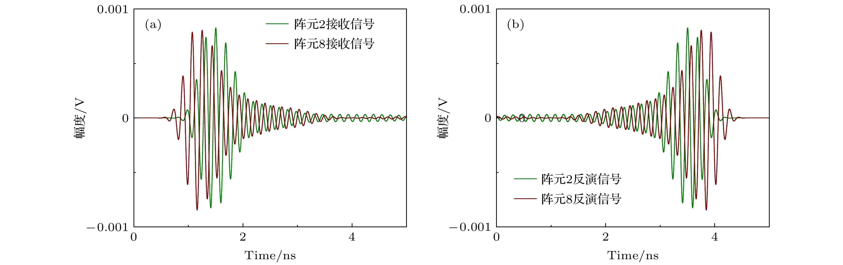
图 3 目标角度为(+30°, 0°)时, 阵列天线单元2和单元8的接收信号和反演信号 (a)接收信号(b)时间反演信号
Figure 3. Received signal and time reversal signal of array antenna element 2 and element 8 when the target angle is (+30°, 0°): (a) The received signal; (b) the excitation signal by time reversal.
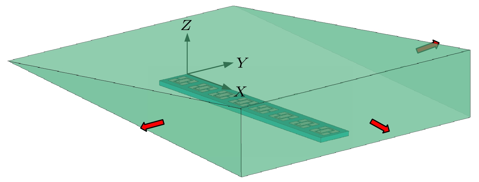
图 4 顶部劈尖天线罩计算模型示意图
Figure 4. Schematic diagram of calculation model of top wedge radome.

图 5 时间反演和传统方法归一化辐射方向图对比(颜色条表示辐射场的相对场强(归一化模值)) (a)目标角度–30°, 5 GHz 传统相扫辐射方向图; (b) 目标角度–30°, 5 GHz 时间反演辐射方向图; (c)目标角度–30°, 6 GHz 传统相扫辐射方向图; (d) 目标角度–30°, 6 GHz 时间反演辐射方向图; (e)目标角度+45°, 5 GHz 传统相扫辐射方向图; (f) 目标角度+45°, 5 GHz 时间反演辐射方向图; (g)目标角度+45°, 6 GHz 传统相扫辐射方向图; (h) 目标角度+45°, 6 GHz 时间反演辐射方向图
Figure 5. Comparison of normalized radiation pattern between time reversal and traditional methods: (a) The 5 GHz traditional phase scan radiation pattern when the target angle is –30°; (b) the 5 GHz time reversal radiation pattern when the target angle is –30°; (c) the 6 GHz traditional phase scanning radiation pattern when the target angle is –30°; (d) the 6 GHz time reversal radiation pattern when the target angle is –30°; (e) the 5 GHz traditional phase scanning radiation pattern when the target angle is +45°; (f) the 5 GHz time reversal radiation pattern when the target angle is +45°; (g) the 6 GHz traditional phase scanning radiation pattern when the target angle is +45°; (h) the 6 GHz time reversal radiation pattern when the target angle is +45°.
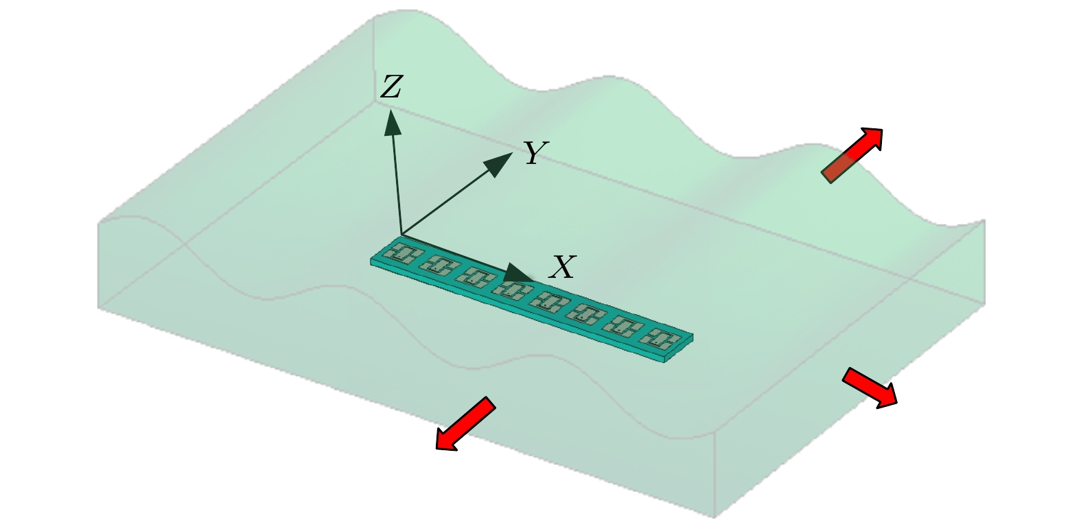
图 6 表面积冰天线罩覆盖在阵列天线
Figure 6. Rrray antenna under the ice on the radome surface.
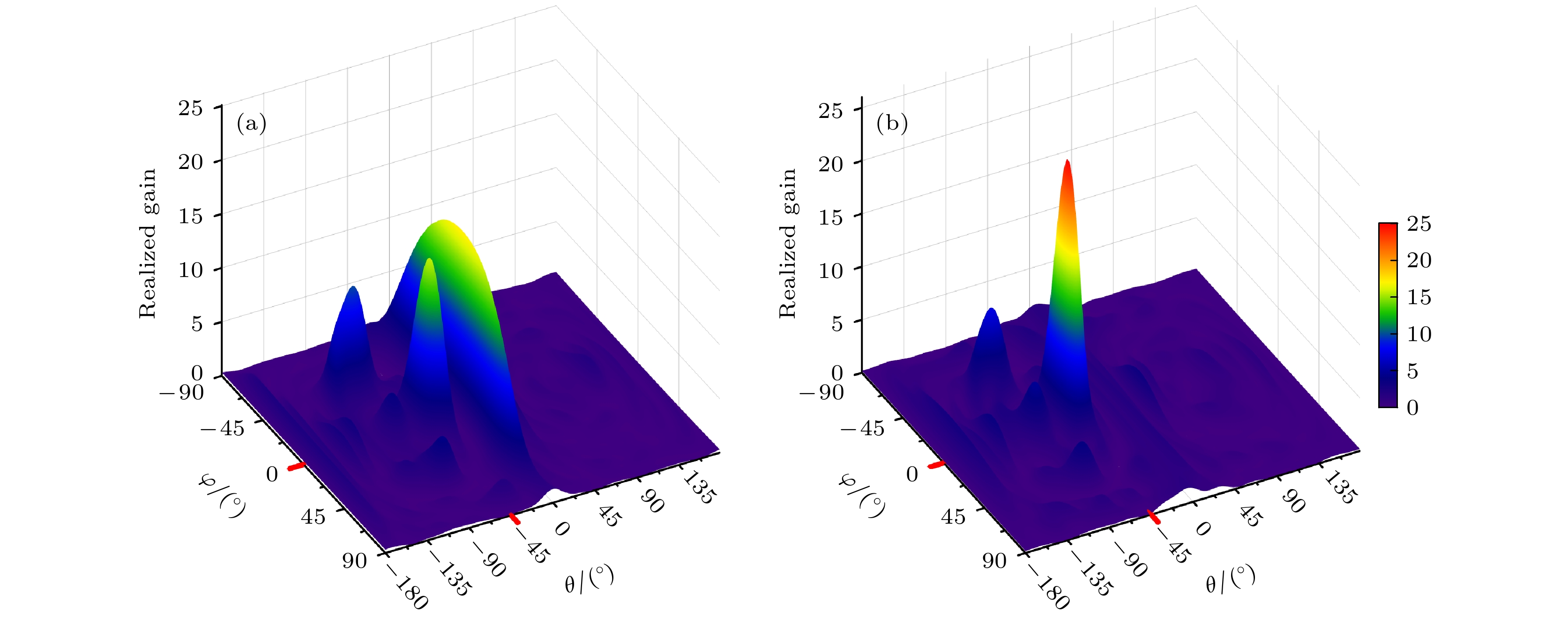
图 7 目标波束指向–45°时传统方法和时间反演方法在远场的实际增益图 (a)传统方法增益图; (b)时间反演方法增益图
Figure 7. Realized gain pattern of target angle –45° (linear): (a) The pattern of traditional method; (b) the pattern of time reversal.
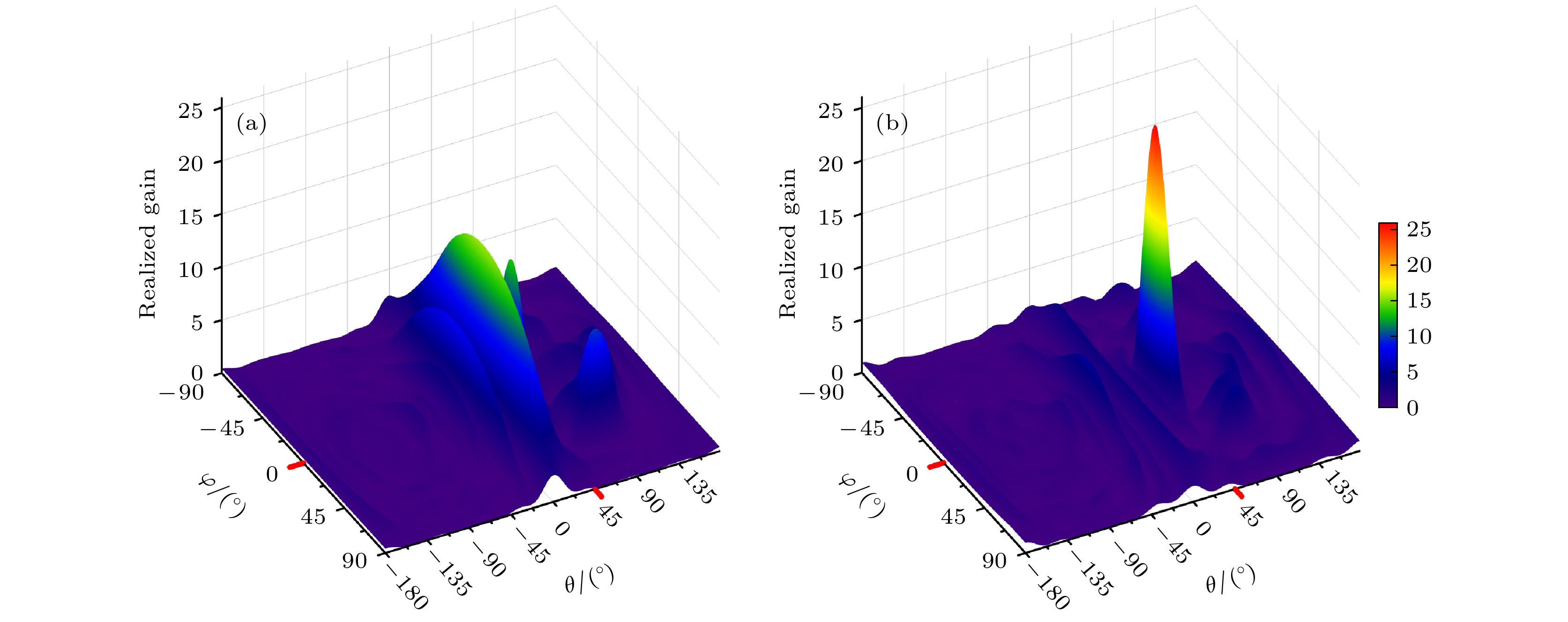
图 8 目标波束指向+45°时传统方法和时间反演方法在远场的实际增益图 (a)传统方法增益图; (b)时间反演方法增益图
Figure 8. Realized gain pattern of target angle +45° (linear): (a) The pattern of traditional method; (b) the pattern of time reversal.
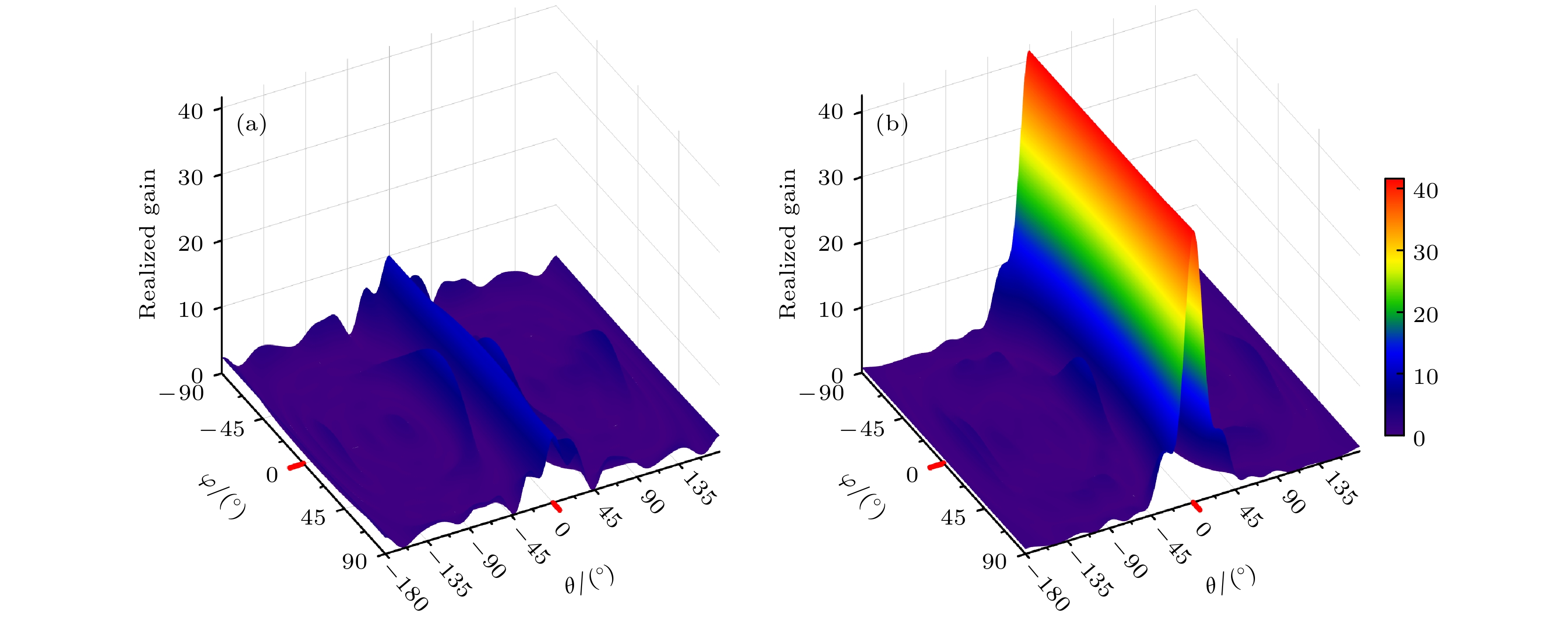
图 9 目标波束指向0°时传统方法和时间反演方法在远场的实际增益图 (a)传统方法增益图; (b)时间反演方法增益图
Figure 9. Realized gain pattern of target angle 0° (linear): (a) The pattern of traditional method; (b) the pattern of time reversal.
表 1 无覆盖阵列天线传统方法与时间反演方法的阵列辐射结果
Table 1. Radiation results of array antenna by traditional method and time reversal.
目标/(°) 传统方法 本文方法 实际波束指向/(°) 目标方向增益/dBi 实际波束指向/(°) 目标方向增益/dBi 5 GHz 6 GHz 5 GHz 6 GHz 5 GHz 6 GHz 5 GHz 6 GHz 0 0 0 13.2 11.4 0 0 13.8 14.9 +15 +14.7 +14.8 11.7 10.4 +14.8 +14.9 13.8 14.7 +30 +29.3 +29.6 13.5 14.2 +29.5 +29.7 13.6 14.2 +45 +43.1 +43.4 13.0 13.2 +43.4 +43.9 13.1 13.2  DownLoad: CSV
表 2 无覆盖阵列天线传统方法与时间反演方法的阵列辐射3 dB宽度对比结果
Table 2. The 3 dB beamwidth of array antenna radiation by traditional method and time reversal.
目标/(°) 传统方法 本文方法 5 GHz 6 GHz 5 GHz 6 GHz 3 dB波束
宽度/(°)0 15.0 12.6 14.9 12.6 +15 15.6 13.1 15.4 13.1 +30 17.2 14.7 17.0 14.8 +45 20.2 17.5 20.1 17.3
DownLoad: CSV
表 3 顶部劈尖天线罩下传统方法与时间反演阵列辐射结果
Table 3. Results of array radiation by traditional method and time reversal under the top wedge radome.
目标/(°) 传统方法 本文方法 实际波束指向/(°) 目标方向增益/dBi 实际波束指向/(°) 目标方向增益/dBi 5 GHz 6 GHz 5 GHz 6 GHz 5 GHz 6 GHz 5 GHz 6 GHz –45 –31.5 –31.7 8.7 9.2 –44.3 –44.2 12.3 12.9 –30 –19.0 –20.5 5.5 10.7 –29.2 –29.3 15.3 16.6 –15 –5.7 –6.1 12.8 11.4 –14.6 –14.7 16.3 17.0 0 +8.3 +8.6 13.2 11.4 +0.3 –0.2 16.8 17.2 +15 +23.7 +25.1 11.7 10.4 +14.3 +14.6 16.2 17.0 +30 +42.2 +38.7 8.4 13.2 +30.6 +29.1 13.6 15.9 +45 无较强主瓣 +42.0 +43.3 14.5 15.1
DownLoad: CSV
表 4 顶部劈尖天线罩下传统方法与时间反演阵列辐射3 dB波束宽度对比结果
Table 4. The 3 dB beam width of array antenna radiation by traditional method and time reversal under top wedge radome.
目标/(°) 传统方法 本文方法 5 GHz 6 GHz 5 GHz 6 GHz 3 dB波束
宽度/(°)–45 17.1 13.9 19.5 18.8 –30 16.5 14.5 16.3 14.1 –15 15.6 12.8 14.9 12.8 0 16.2 13.2 13.4 12.9 +15 19.0 14.7 17.5 13.0 +30 26.1 14.1 16.1 14.0 +45 无较强主瓣 19.3 13.8
DownLoad: CSV
-
[1] 张强 2014 天线罩理论与设计方法 (北京: 国防工业出版社) 第3, 4页
Zhang Q 2014 Radome Theory and Design Methods (Vol. 1) (Beijing: National Defense Industry Press) pp3, 4 (in Chinese)
[2] 刘晓春 2017 雷达天线罩电性能设计技术 (北京: 航空工业出版社) 第1页
Liu X C 2017 Radome Electrical Performance Design Technology (Vol. 1) (Beijing: Aviation Industry Press) p1 (in Chinese)
[3] Cady W M, Karelity M B, Turner Lous A 1948 Radar Scanners and Radomes (Vol. 26, Chapter. 13) (New York: MicGraw-Hill Book Company)
[4] Kay A L 1965 IEEE Trans. Antennas Propag. 13 188
Google Scholar
[5] 张强 2014 天线罩理论与设计方法 (北京: 国防工业出版社) 第51—59页
Zhang Q 2014 Radome Theory and Design Methods (Vol. 1) (Beijing: National Defense Industry Press) pp51–59 (in Chinese)
[6] [7] Paris D 1970 IEEE Trans. Antennas Propag. 18 7
Google Scholar
[8] Deschamps G A 1972 Proceedings of the IEEE 60 1022
Google Scholar
[9] 张强 1996 现代雷达 18 57
Zhang Q 1996 Modern Radar 18 57
[10] 张强 2014 天线罩理论与设计方法 (北京: 国防工业出版社) 第68, 69页
Zhang Q 2014 Radome Theory and Design Methods (Vol. 1) (Beijing: National Defense Industry Press) pp68, 69 (in Chinese)
[11] Mittea R, Chan C H, Cwik T 1988 Proceedings of the IEEE 76 1593
Google Scholar
[12] Shifflett J A 1997 IEEE Antennas Propag. Mag. 39 73
Google Scholar
[13] Xu W Y, Zong Y, Peng L, Qiu Y Y 2021 IEEE Trans. Antennas Propag. 69 2443
Google Scholar
[14] Xu W Y, Duan B Y, Peng L, Qiu Y Y 2017 IEEE Trans. Antennas Propag. 65 3175
Google Scholar
[15] Zhang Q 2009 3rd European Conference on Antennas and Propagation Berlin, Germany, March 23–27, 2009 p3718
[16] Liu Y, Zhao X X, Ouyang S X, Liu J 2018 The 8th Youth Science and Technology Forum of CAAC Jiangmen, China, November 5, 2018 p989 (in Chinese) [刘毅, 赵晓霞, 欧阳绍修, 刘建平 2018 第八届中国航空学会青年科技论坛 中国江门, 2018年11月5日 p989]
[17] H A Burger 2011 IEEE International Symposium on Antennas and Propagation (APSURSI), Spokane, August 25 p313
[18] Wu R Y, Li Y B, Wu W, Shi C B, Cui T J 2017 IEEE Trans. Antennas Propag. 65 3481
Google Scholar
[19] Luo X Y, Guo W L, Chen K, Zhao J M, Jiang T, Liu Y, Feng Y J 2021 IEEE Trans. Antennas Propag. 69 3332
Google Scholar
[20] Zhang N, Chen K, Zhao J M, Hu Q, Tang K, Zhao J M, Feng Y J 2022 IEEE Trans. Antennas Propag. 70 7403
Google Scholar
[21] 张娜, 赵建民, 陈克, 赵俊明, 姜田, 冯一军 2021 物理学报 70 178102
Google Scholar
Zhang N, Zhao J M, Chen K, Zhao J M, Jiang T, Feng Y J 2021 Acta Phys. Sin. 70 178102
Google Scholar
[22] Fink M 1997 Phys. Today 50 34
Google Scholar
[23] 梁木生, 王秉中, 章志敏, 丁帅, 臧锐 2013 物理学报 62 058401
Google Scholar
Liang M S, Wang B Z, Zhang Z M, Ding S, Zang R 2013 Acta Phys. Sin. 62 058401
Google Scholar
[24] 张知原, 李冰, 刘仕奇, 张洪林, 胡斌杰, 赵德双, 王楚楠 2022 物理学报 71 014101
Google Scholar
Zhang Z Y, Li B, Liu S Q, Zhang H L, Hu B J, Zhao D S, Wang C N 2022 Acta Phys. Sin. 71 014101
Google Scholar
[25] 张倩倩, 尹成友, 李安琪 2022 微波学报 038 18
Zhang Q Q, Yi C Y, Li A Q 2022 Journal of Microwaves 038 18
[26] 陈伟, 陈蕾, 邹林, 史小卫, 李桂红, 洪玮 2022 电波科学学报 37 956
Chen W, Chen L, Zou L, Shi X W, Li G H, Hong W 2022 Chinese Journal of Radio Science 37 956
[27] Jia Q S, Ding S, Dong H B, Han X, Zhu Z J, Wang B Z, Huang Y M, Maurizio Bozzi 2021 IEEE Access. 9 30677
Google Scholar
[28] Zhao D S, Jin Y W, Wang B Z, Zang R 2012 IEEE Trans. Antennas Propag. 60 164
Google Scholar
[29] Nguyen H T, Kovcs I Z, P C F Eggers 2006 IEEE Trans. Antennas Propag. 54 3216
Google Scholar
[30] 王秉中, 王任 2020 时间反演电磁学 (北京: 科学出版社) 第202—206页
Wang B Z, Wang R 2020 Time Reversal Electromagnetism (Beijing: Science Press) pp202–206 (in Chinese)
[31] Farr E G, Baum C E 1998 Time Domain Characterization of Antennas with TEM Feeds (Sensor and Simulation Notes) Note 426
[32] Baum C E 2002 IEEE Trans. Electromagn. Compat. 44 18
Google Scholar
[33] Smith G S 2004 IEEE Trans. Antennas Propag. 52 1568
Google Scholar
[34] 约翰 J D, 马赫夫克 R J 著 (章文勋 译) 2019 天线 (北京: 电子工业出版社) 第16—19页
Kraus J D, Marhefka R J (translated by Zhang W X) 2019 Antennas: For All Applications (Beijing: Publishing House of Electronics Industry) pp16–19 (in Chinese)
[35] Wi S H, Lee Y S, Yook J G 2007 IEEE Trans. Antennas Propag. 55 1196
Google Scholar
[36] Gao X, Felsen L 1985 IEEE Trans. Antennas Propag. 33 963
Google Scholar

 DownLoad:
Catalog
Metrics
- Abstract views: 7170
- PDF Downloads: 92
- Cited By: 0
