


-
Microwave discharge neutralizer is an important part of microwave discharge ion thruster system, which plays a vital role in maintaining potential balance between spacecraft and neutralizing ion beam. Its electron extraction property directly affects the operation condition of ion thruster system. In order to break through the power limit of miniature microwave discharge ion thruster, a magnet array microwave discharge ion thruster system is designed and tested. In the experiment on finalizing magnetic field structure of magnet array microwave discharge neutralizer, an interesting phenomenon is found that the I-V curves of electron current, after rotating the magnetic array orientation, are very different. Defining forward direction of magnet array can normally extract electrons, then backward direction of magnet array can hardly extract electrons. Because the diameter of discharge chamber is only 10 mm, it is too small to perform Langmuir probe diagnosis. And thus, an integrative particle-in-cell method is used to simulate the neutralizer operation processes of two different magnetic field structures, and for the sake of accuracy, real vacuum permittivity is used. The simulation results show good consistence with experimental phenomenon. In the initial discharge process, it is found that the magnetic field gradient leads to different plasma distributions; in electron extraction process, it is found that the potential distribution near the orifice determines the electron extraction property of the neutralizer. Through comparing the plasma parameter distributions under different magnetic field structures and operating voltages, an assumption that the ion is an important factor in electron extraction process is proposed. Then, a simulation that ions disappear artificially outside the orifice is conducted, and the simulation results show that electrons cannot be effectively extracted without ions near the orifice. According to the simulation and experiment results, two necessary conditions are summarized for electron extraction of the neutralizer. The first condition is magnetic field structure: the magnetic field gradient should point towards the orifice to guide plasma migration towards the orifice, the second one is potential distribution: there should be enough ions to lift the potential near the orifice for reducing or breaking the potential well. These two conditions can help understand the electron extraction mechanism of microwave discharge neutralizer and provide theoretical reference for optimizing the performance of neutralizer in future.
-
Keywords:
- electron cyclotron resonance /
- neutralizer /
- electron extraction
[1] Nono A, Morishita T, Hosoda S, Tsukizaki R, Nishiyama K 2023 Acta Astronaut. 212 130
 Google Scholar
[2] 杨涓, 牟浩, 耿海, 吴先明 2023 推进技术 44 2208095
Yang J, Mou H, Geng H, Wu X M 2023 J. Propuls. Tech. 44 2208095
[3] Koizumi H, Komurasaki K, Aoyama J, Yamaguchi K 2018 J. Propuls. Power. 34 960
Google Scholar
[4] Koizumi H, Komurasaki K, Aoyama J, Yamaguchi K 2014 Trans. JSASS Aerospace Tech. 12 1884
[5] Tsukizaki R, Ise T, Koizumi H, Togo H, Nishiyama K, Kuninaka H 2014 J. Propuls. Power. 30 91
[6] Barquero S, Tabata K, Tsukizaki R, Merino M, Navarro-Cavallé J, Nishiyama K 2023 Acta Astronaut. 211 750
Google Scholar
[7] Sekine H, Minematsu R, Ataka Y, Ominetti P, Koizumi H, Komurasaki K 2022 J. Appl. Phys. 131 093302
Google Scholar
[8] Motoki T, Takasaki D, Koizumi H, Ataka Y, Komurasaki K, Takao Y 2022 Acta Astronaut. 196 231
Google Scholar
[9] Sato Y, Koizumi H, Nakano M, Takao Y 2020 Phys. Plasmas. 27 063505
Google Scholar
[10] Tsuru T, Kondo S, Yamamoto N, Nakashima H 2009 Trans. JSASS Aerospace Tech. 7 163
[11] Yamamoto N, Maeda Y, Nakashima H, Watanabe H, Funaki I 2016 Trans. JSASS Aerospace Tech. 59 100
[12] Foster J E, Patterson M J 2005 J. Propuls. Power. 21 862
Google Scholar
[13] 夏旭, 杨涓, 耿海, 吴先明, 付瑜亮, 牟浩, 谈人玮 2022 物理学报 71 045201
Google Scholar
Xia X, Yang J, Geng H, Wu X M, Fu Y L, Mou H, Tan R W 2022 Acta Phys. Sin. 71 045201
Google Scholar
[14] Masui H, Tashiro Y, Yamamoto N, Nakashima H, Funaki I 2006 Trans. JSASS Aerospace Tech. 49 87
[15] Kubota K, Watanabe H, Yamamoto N, Nakashima H, Miyasaka T, Funaki I 2014 50th AIAA/ASME/SAE/ASEE Joint Propulsion Conference Cleveland, OH, July 28–30, 2014 pp1–12
[16] 孟海波, 杨涓, 黄文斌, 夏旭, 付瑜亮, 胡展 2019 宇航学报 40 1478
Google Scholar
Meng H B, Yang J, Huang W B, Xia X, Fu Y L, Hu Z 2019 J. Astronaut. 40 1478
Google Scholar
[17] Hiramoto K, Nakagawa Y, Koizumi H, Takao Y 2017 Phys. Plasmas 24 064504
Google Scholar
[18] Sato Y, Koizumi H, Nakano M, Takao Y 2019 J. Appl. Phys. 126 243302
Google Scholar
[19] Fu Y L, Yang J, Geng H, Wu X M, Hu Z, Xia X 2021 Vacuum 184 109932
Google Scholar
[20] 付瑜亮 2022 博士学位论文(西安: 西北工业大学)
Fu Y L 2022 Ph. D. Dissertation (Xi’an: Northwestern Polytechnical University
[21] 付瑜亮, 张思远, 杨谨远, 孙安邦, 王亚楠 2024 物理学报 73 095203
Google Scholar
Fu Y L, Zhang S Y, Yang J Y, Sun A B, Wang Y N 2024 Acta Phys. Sin. 73 095203
Google Scholar
[22] Fu Y L, Yang J, Mou H, Tan R W, Xia X, Gao Z Y 2022 Comput. Phys. Commun. 278 8395
-
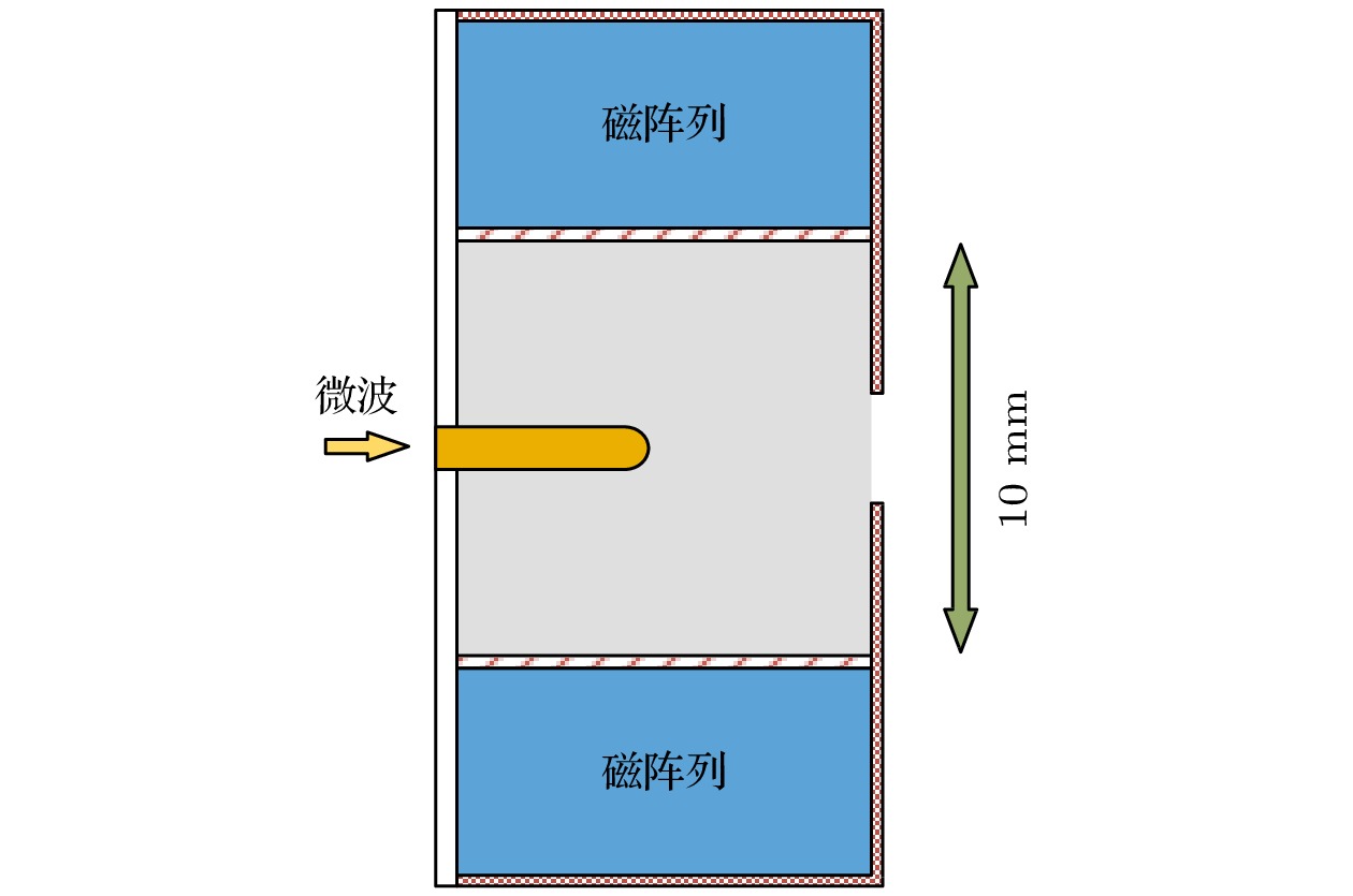
图 1 磁阵列微波放电中和器结构简图
Figure 1. Structure diagram of magnet array microwave discharge neutralizer.
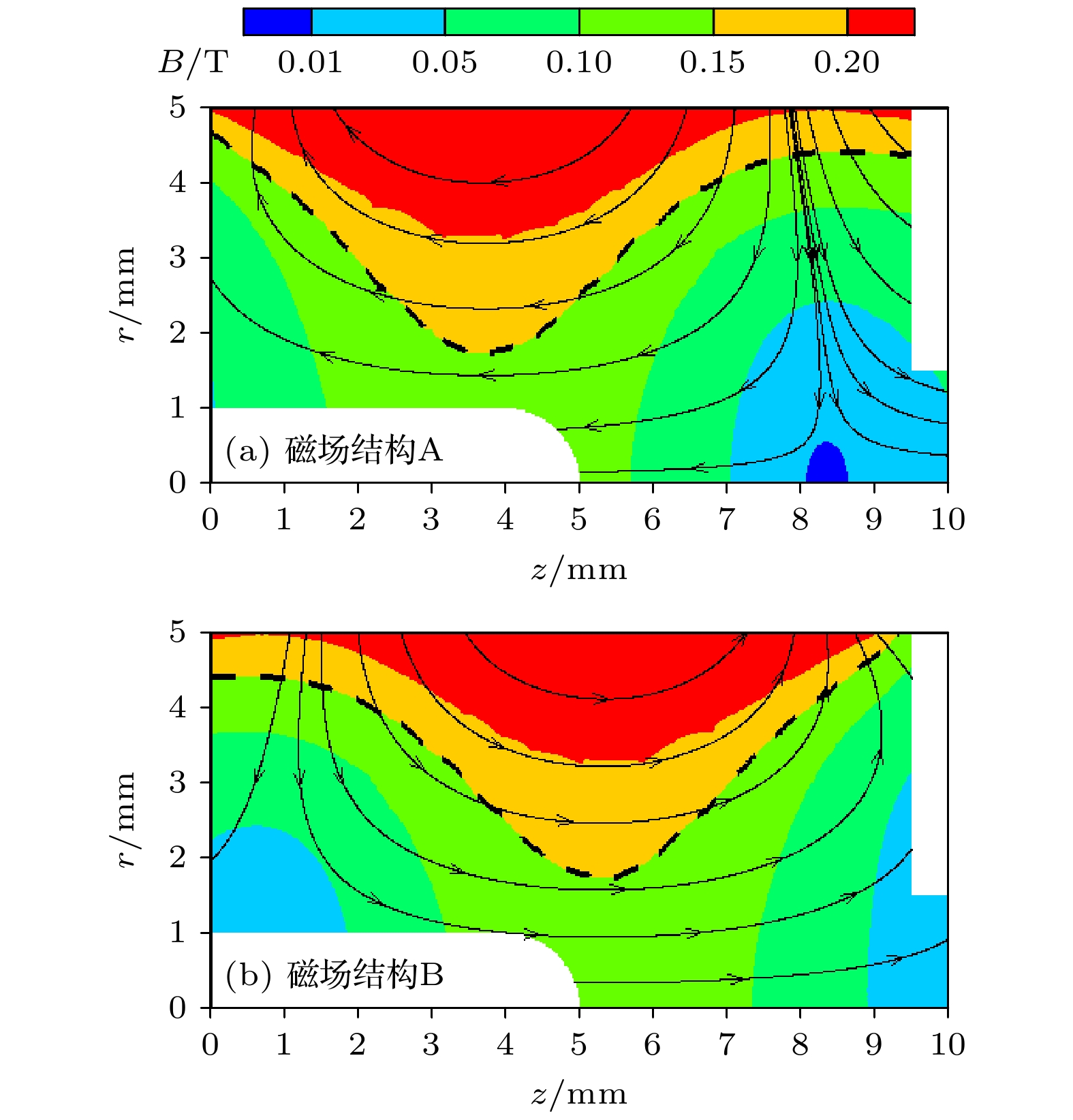
图 2 磁阵列微波放电中和器的磁场结构
Figure 2. Magnetic field of magnet array microwave discharge neutralizer.
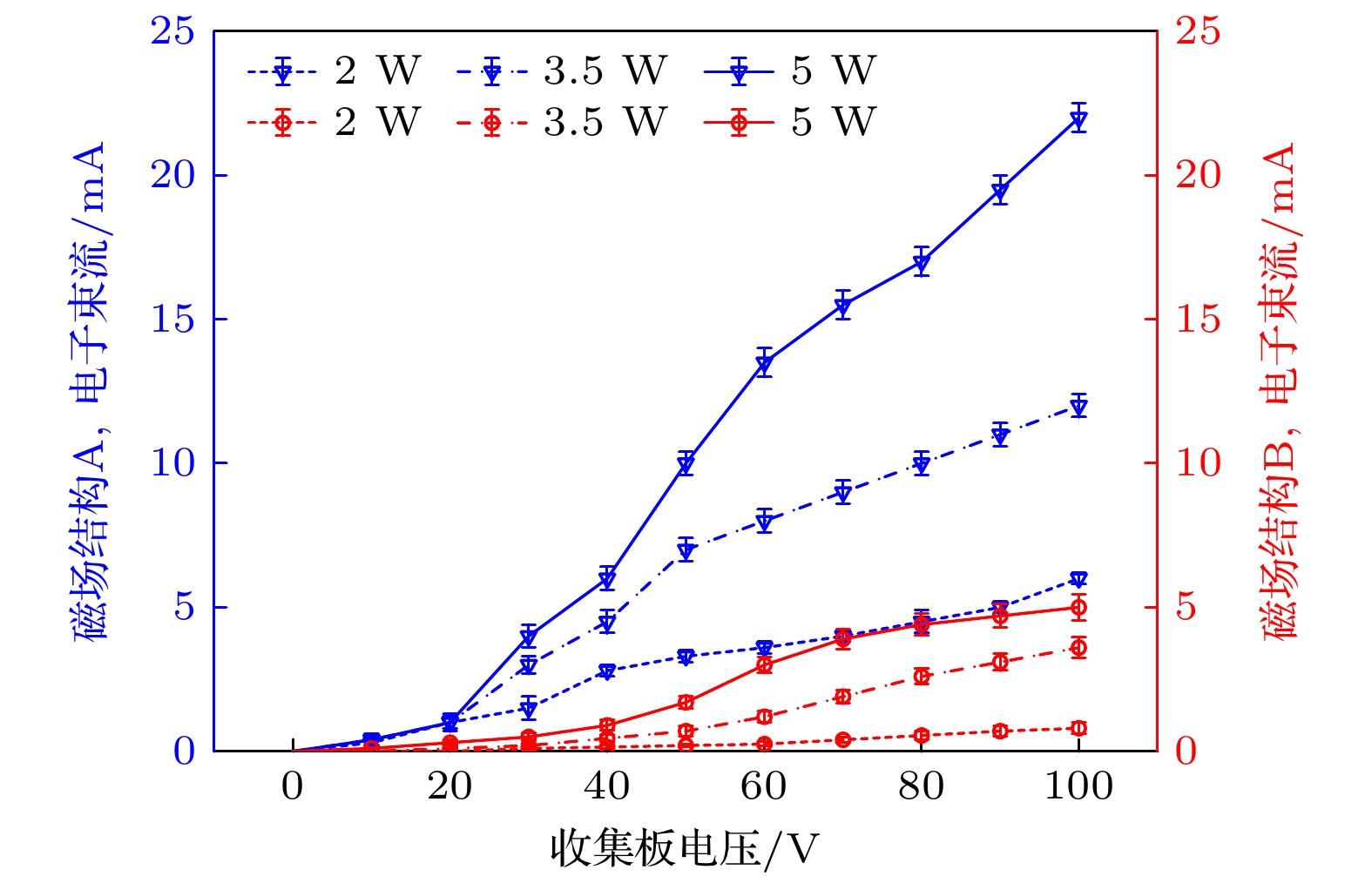
图 3 磁阵列微波放电中和器伏安特性曲线
Figure 3. I-V curves of magnet array microwave discharge neutralizer.
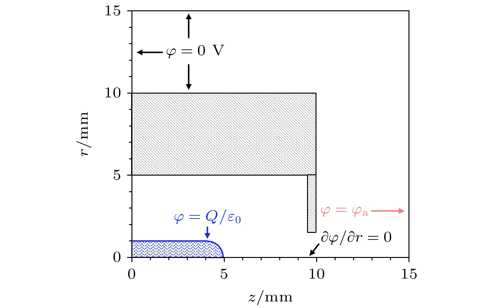
图 4 计算域和边界条件
Figure 4. Calculation region and boundary condition setting.
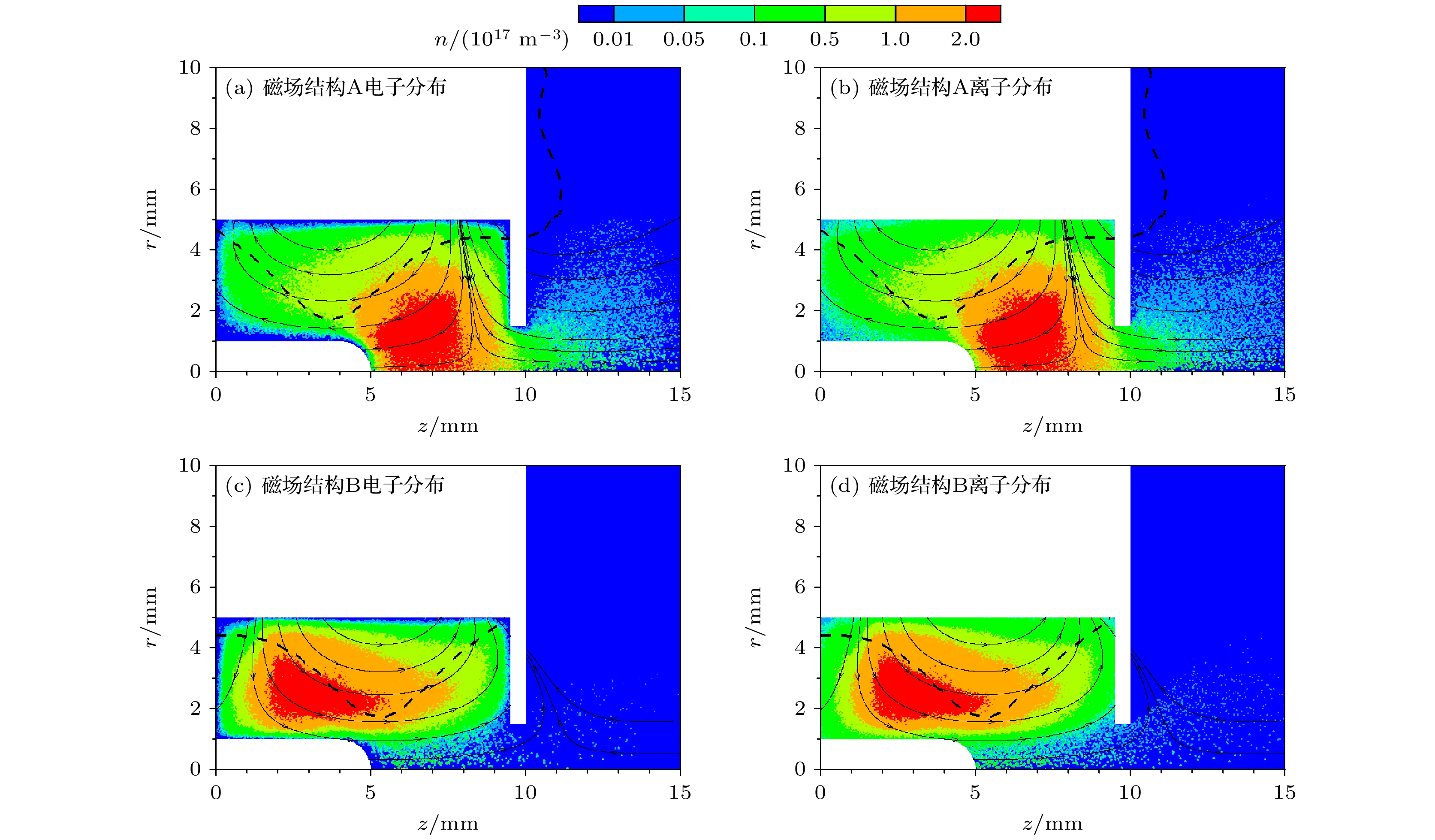
图 5 初始放电仿真结果 (a)磁场结构A的电子密度分布; (b)磁场结构A的离子密度分布; (c)磁场结构B的电子密度分布; (d)磁场结构B的离子密度分布
Figure 5. Initial discharge simulation results: (a) Electron density distribution of magnetic field structure A; (b) the ion density distribution of magnetic field structure A; (c) the electron density distribution of magnetic field structure B; (d) the ion density distribution of magnetic field structure B.
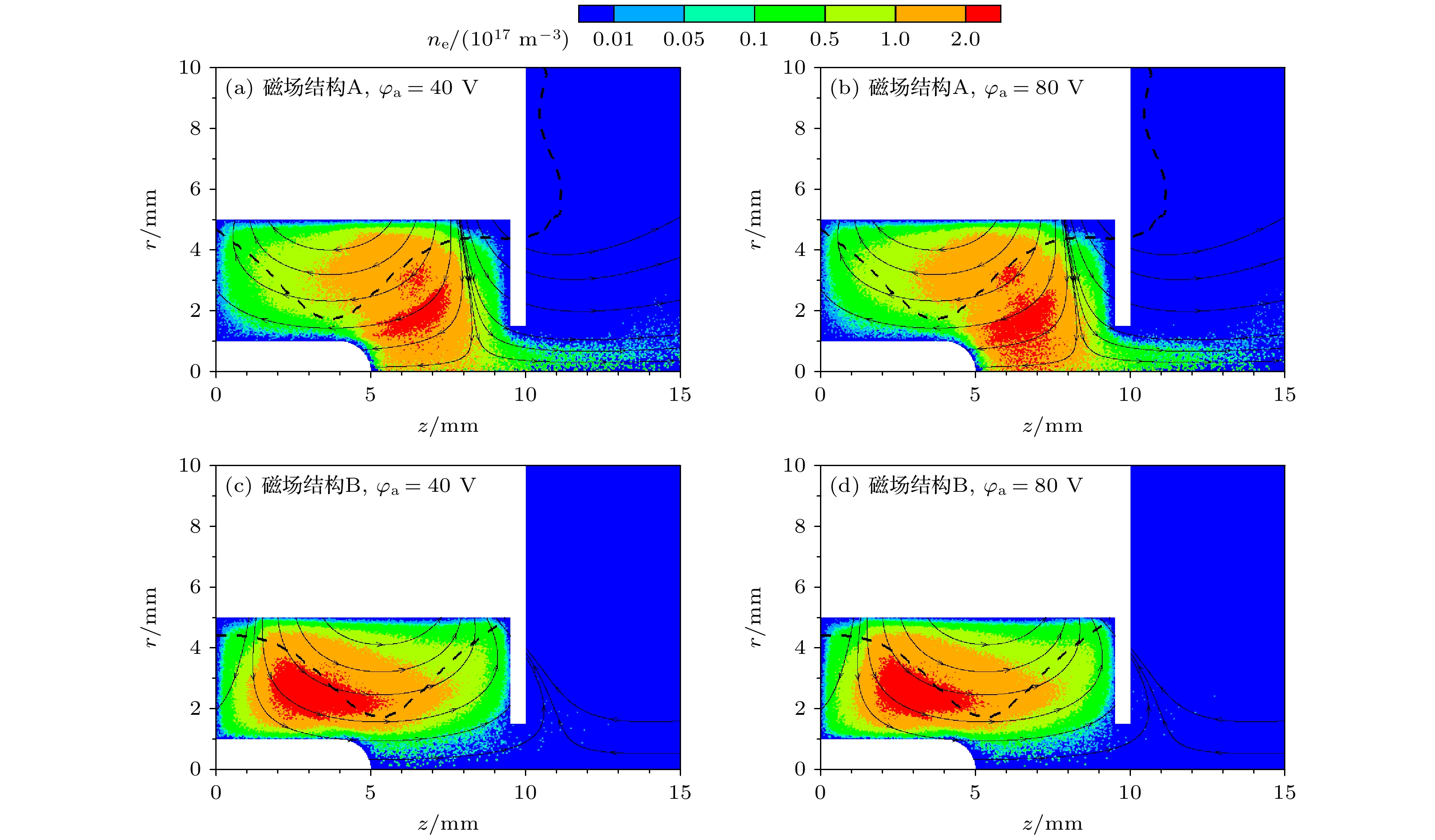
图 6 电子引出仿真结果 (a)磁场结构A, $ {\varphi }_{{\mathrm{a}}} $ = 40 V; (b)磁场结构A, $ {\varphi }_{{\mathrm{a}}} $=80 V; (c)磁场结构B, $ {\varphi }_{{\mathrm{a}}} $ = 40 V; (d)磁场结构B, $ {\varphi }_{{\mathrm{a}}} $ = 80 V
Figure 6. Simulation results of electron beam in extraction stage: (a) Magnetic field structure A, $ {\varphi }_{{\mathrm{a}}} $=40 V; (b) Magnetic field structure A, $ {\varphi }_{{\mathrm{a}}} $ = 80 V; (c) Magnetic field structure B, $ {\varphi }_{{\mathrm{a}}} $ = 40 V; (d) Magnetic field structure B, $ {\varphi }_{{\mathrm{a}}} $ = 80 V.
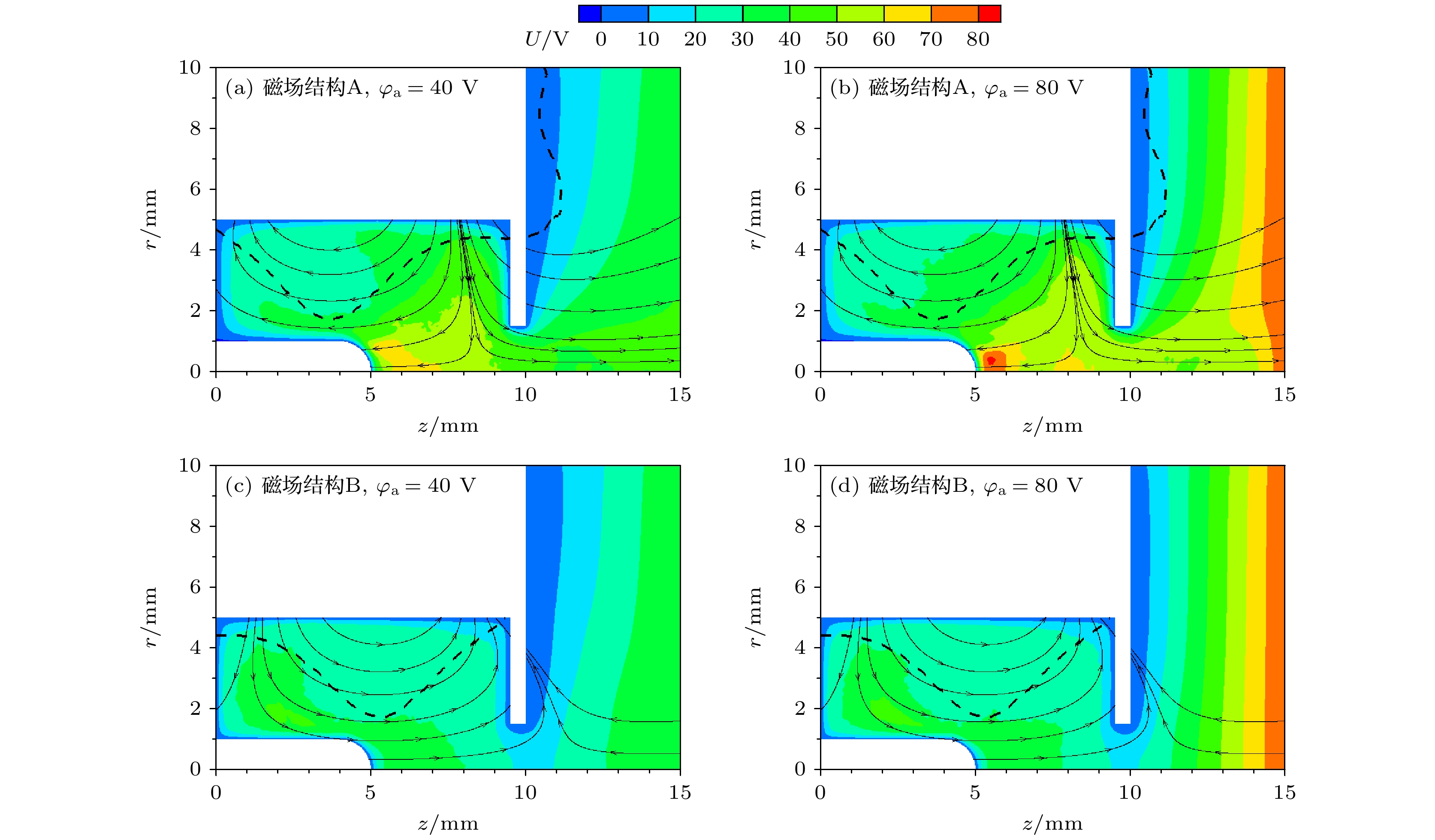
图 7 电子引出阶段电势变化 (a)磁场结构A, $ {\varphi }_{{\mathrm{a}}} $ = 40 V; (b)磁场结构A, $ {\varphi }_{{\mathrm{a}}} $=80 V; (c)磁场结构B, $ {\varphi }_{{\mathrm{a}}} $ = 40 V; (d)磁场结构B, $ {\varphi }_{{\mathrm{a}}} $ = 80 V
Figure 7. Potential distribution in extraction stage: (a) Magnetic field structure A, $ {\varphi }_{{\mathrm{a}}} $ = 40 V; (b) magnetic field structure A, $ {\varphi }_{{\mathrm{a}}} $ = 80 V; (c) magnetic field structure B, $ {\varphi }_{{\mathrm{a}}} $ = 40 V; (d) magnetic field structure B, $ {\varphi }_{{\mathrm{a}}} $=80 V.
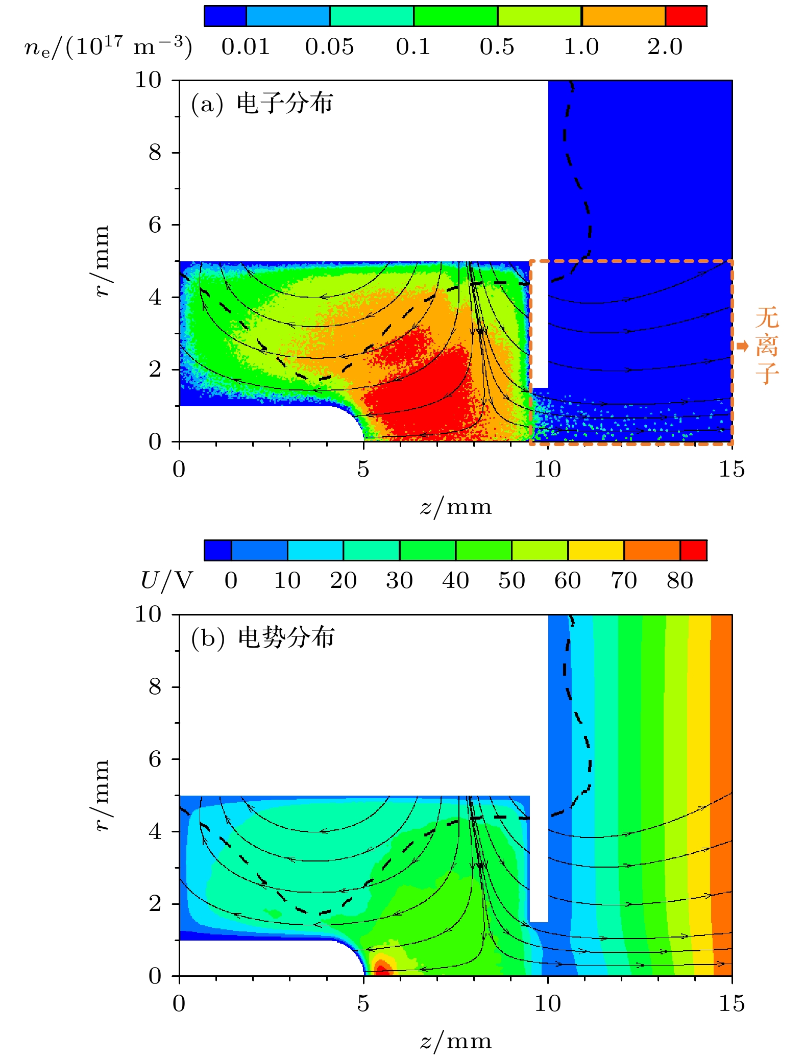
图 8 假设引出孔外无离子的仿真结果 (a)电子分布; (b)电势分布
Figure 8. Electron beam (a) and potential distribution (b) assuming no ion outside orifice.
表 1 参数设置
Table 1. Simulation parameter setting.
参数 设定值 微波频率/GHz 4.2 微波功率/W 1 氙气流量/sccm 0.3 初始等离子体密度/m–3 1 × 10¹⁶ 初始宏粒子数量 10000 时间步长/s 1 × 10–11  DownLoad: CSV
-
[1] Nono A, Morishita T, Hosoda S, Tsukizaki R, Nishiyama K 2023 Acta Astronaut. 212 130
Google Scholar
[2] 杨涓, 牟浩, 耿海, 吴先明 2023 推进技术 44 2208095
Yang J, Mou H, Geng H, Wu X M 2023 J. Propuls. Tech. 44 2208095
[3] Koizumi H, Komurasaki K, Aoyama J, Yamaguchi K 2018 J. Propuls. Power. 34 960
Google Scholar
[4] Koizumi H, Komurasaki K, Aoyama J, Yamaguchi K 2014 Trans. JSASS Aerospace Tech. 12 1884
[5] Tsukizaki R, Ise T, Koizumi H, Togo H, Nishiyama K, Kuninaka H 2014 J. Propuls. Power. 30 91
[6] Barquero S, Tabata K, Tsukizaki R, Merino M, Navarro-Cavallé J, Nishiyama K 2023 Acta Astronaut. 211 750
Google Scholar
[7] Sekine H, Minematsu R, Ataka Y, Ominetti P, Koizumi H, Komurasaki K 2022 J. Appl. Phys. 131 093302
Google Scholar
[8] Motoki T, Takasaki D, Koizumi H, Ataka Y, Komurasaki K, Takao Y 2022 Acta Astronaut. 196 231
Google Scholar
[9] Sato Y, Koizumi H, Nakano M, Takao Y 2020 Phys. Plasmas. 27 063505
Google Scholar
[10] Tsuru T, Kondo S, Yamamoto N, Nakashima H 2009 Trans. JSASS Aerospace Tech. 7 163
[11] Yamamoto N, Maeda Y, Nakashima H, Watanabe H, Funaki I 2016 Trans. JSASS Aerospace Tech. 59 100
[12] Foster J E, Patterson M J 2005 J. Propuls. Power. 21 862
Google Scholar
[13] 夏旭, 杨涓, 耿海, 吴先明, 付瑜亮, 牟浩, 谈人玮 2022 物理学报 71 045201
Google Scholar
Xia X, Yang J, Geng H, Wu X M, Fu Y L, Mou H, Tan R W 2022 Acta Phys. Sin. 71 045201
Google Scholar
[14] Masui H, Tashiro Y, Yamamoto N, Nakashima H, Funaki I 2006 Trans. JSASS Aerospace Tech. 49 87
[15] Kubota K, Watanabe H, Yamamoto N, Nakashima H, Miyasaka T, Funaki I 2014 50th AIAA/ASME/SAE/ASEE Joint Propulsion Conference Cleveland, OH, July 28–30, 2014 pp1–12
[16] 孟海波, 杨涓, 黄文斌, 夏旭, 付瑜亮, 胡展 2019 宇航学报 40 1478
Google Scholar
Meng H B, Yang J, Huang W B, Xia X, Fu Y L, Hu Z 2019 J. Astronaut. 40 1478
Google Scholar
[17] Hiramoto K, Nakagawa Y, Koizumi H, Takao Y 2017 Phys. Plasmas 24 064504
Google Scholar
[18] Sato Y, Koizumi H, Nakano M, Takao Y 2019 J. Appl. Phys. 126 243302
Google Scholar
[19] Fu Y L, Yang J, Geng H, Wu X M, Hu Z, Xia X 2021 Vacuum 184 109932
Google Scholar
[20] 付瑜亮 2022 博士学位论文(西安: 西北工业大学)
Fu Y L 2022 Ph. D. Dissertation (Xi’an: Northwestern Polytechnical University
[21] 付瑜亮, 张思远, 杨谨远, 孙安邦, 王亚楠 2024 物理学报 73 095203
Google Scholar
Fu Y L, Zhang S Y, Yang J Y, Sun A B, Wang Y N 2024 Acta Phys. Sin. 73 095203
Google Scholar
[22] Fu Y L, Yang J, Mou H, Tan R W, Xia X, Gao Z Y 2022 Comput. Phys. Commun. 278 8395

 DownLoad:
Catalog
Metrics
- Abstract views: 3275
- PDF Downloads: 145
- Cited By: 0
