


-
基于偏振调制的三维成像激光雷达, 具有测量范围远、测量精度较高、成像速度快、无运动伪像等优点, 同时不受其他调制方式中增强电荷耦合器件、雪崩光电二极管阵列探测器工艺复杂、易饱和损坏等缺点限制, 但存在需要双相机、成像视场角受电光晶体限制、成像质量易受到入射角度及云雾等大气条件影响等缺点. 为克服上述缺点, 本文提出采用偏振成像激光雷达与短波红外变焦光学系统共孔径复合的方式, 构建双模目标探测成像系统. 开展偏振成像激光雷达与短波红外复合光学系统设计研究, 使用光学设计软件完成系统光学设计, 并对完成系统像质分析; 使用光学仿真软件对光学系统成像过程仿真; 分析仿真结果表明所设计光学系统成像质量良好、设计正确可行. 本文所采用方法为偏振调制成像激光雷达研究提供一种新思路.
The basic principle of three-dimensional (3D) imaging lidar-an active imaging technology, is parallel laser ranging. Compared with traditional passive sensor imaging and microwave radar, the 3D imaging lidar has obvious advantages, so it promises to possess a wide application prospect. Non-scanning 3D imaging lidar has seven modulation modes. Among them, the 3D imaging lidar based on polarization modulation has the advantages of large measurement range, high measurement accuracy, fast imaging speed, and no motion artifacts. At the same time, it is not limited by other modulation methods, such as intensified charge coupled device and avalanche photodiode array detectors, and its process is complex but easy to saturate and damage. However, its disadvantage is that it requires two cameras, electro-optic crystal limits the imaging field of view, and is easily affected by atmospheric conditions such as incident angle and cloud and mist. In order to overcome the above shortcomings, in this paper we propose to use polarization imaging lidar and short-wave infrared zoom optical system to construct a dual-mode target detection imaging system by means of common aperture, which can not only reduce the volume of the two systems and solve the coaxial problem of the two systems, but also solve the problems such as the influence of atmospheric conditions (small viewing angle, incident angle and cloud and mist) on imaging quality of polarization modulation imaging lidar and the limitation of low energy of short-wave infrared imaging targets. According to the above ideas, the design and research of polarization imaging lidar and shortwave infrared composite optical system are carried out. The optical design software is used to complete the optical design of the telescope group, shortwave infrared imaging lens group, polarization modulation lens group and the system as a whole. In the telescope group the off-axis three-mirror structure is used to solve the blocking problem of the center of the field of view, and in the shortwave infrared lens group the type of mobile zoom compensation group is used to realize zooming. Analysis of the image quality of the optical system shows that the designed optical system has high imaging quality and its optical design meets the requirements for system design. The optical simulation software is used to simulate the imaging process of the optical system. The results show below. The polarization imaging lidar and shortwave infrared imaging have high quality, the stray light has little influence on the imaging of the system, the target edge imaging is clear, and the independent square targets with a 1-m in diameter can be distinguished. The field of view of the short-wave infrared short-focus mode is 9 times that of the long-focus mode. The shortwave infrared telescopic mode is basically consistent with the field of view of polarization imaging lidar. The received illuminance value of polarization imaging lidar is about 2.4 times that of short-wave infrared long focal length mode. The overall energy distribution of polarization imaging lidar is more balanced, and the imaging effect is better. The method adopted in this paper provides a new idea for studying the polarization modulated imaging lidar. The next step in experimental research is to complete the physical processing, assembly and adjustment, and selection of suitable targets. -
Keywords:
- three-dimensional imaging /
- lidar /
- polarization /
- short wave infrared /
- optical design
[1] 严惠民, 倪旭翔, 陈奇霖, 陆祖康 2000 中国激光 27 861
 Google Scholar
Yan H M, Ni X X, Chen Q L, Lu Z K 2000 Chin. J. Lasers 27 861
Google Scholar
[2] McManamon P F 2012 Opt. Eng. 51 060901
Google Scholar
[3] Molebny V, Steinvall O 2014 Proc. SPIE 9080 908002
[4] 刘博, 于洋, 姜朔 2019 光电工程 46 190167
Google Scholar
Li B, Yu Y, Jiang S 2019 Opto-Electronic Eng. 46 190167
Google Scholar
[5] 曹秋生 2016 红外与激光工程 45 1003002
Google Scholar
Cao Q S 2016 Infrared Laser Eng. 45 1003002
Google Scholar
[6] 卜禹铭, 杜小平, 曾朝阳, 赵继广, 宋一铄 2018 中国光学 11 711
Google Scholar
Bu Y M, Du X P, Zeng C Y, Zhao J G, Song Y S 2018 Chin. OPT. 11 711
Google Scholar
[7] 姜凯 2013 博士学位论文 (西安: 中国科学院西安光学精密机械研究所)
Jiang K 2013 Ph. D. Dissertation (Xi'an: Xi'an Institute of Optics and Precision Mechanics, Chinese Academy of Sciences) (in Chinese)
[8] 李荣刚, 张兴德, 孙昌锋, 刘琳, 李江勇, 王诚 2013 激光与红外 43 128
Li R G, Zhang X D, Sun C F, Liu L, Li J Y, Wang C 2013 Laser Infrared 43 128
[9] 贾冰, 曹国华, 吕琼莹, 丁红昌 2016 红外与激光工程 46 218001
Google Scholar
Jia B, Cao G H, Lv Q Y, Ding H C 2016 Infrared Laser Eng. 46 218001
Google Scholar
[10] 丛海佳 2013 硕士学位论文 (哈尔滨: 哈尔滨工业大学)
Cong H J 2013 M.S. Thesis (Haerbin: Harbin Institute of Technology) (in Chinese)
[11] Jo S, Kong H J, Bang H 2016 Opt. Express. 24 A1580
Google Scholar
[12] Chen Z, Li B, Wang S J, Liu E H 2018 Appl. Opt. 57 7750
Google Scholar
[13] 陈臻 2017 博士学位论文 (成都: 中国科学院研究生院)
Chen Z 2017 Ph. D. Dissertation (Chengdu: Graduate School of Chinese Academy of Sciences) (in Chinese)
[14] 白廷柱, 金伟其 2015 光电成像原理与技术 (北京: 北京理工大学出版社) 第48−52页
Bai T Z, Jin W Q 2015 Opto-electric Imaging Technology (Beijing: Beijing Institute of Technology Press) pp48−52 (in Chinese)
[15] 邢振冲 2018 博士学位论文 (长春: 中国科学院长春光学精密机械与物理研究所)
Xing Z C 2018 Ph. D. Dissertation (Changchun: Changchun Institute of Optics, Fine Mechanics and Physics, Chinese Academy of Sciences) (in Chinese)
[16] 常军, 张晓芳, 张柯, 牛亚军 2017 现代反射变焦光学系统 (北京: 国防工业出版社) 第6−10页
Chang J, Zhang X F, Zhang K, Niu Y J 2017 Modern Reflective Zoom Optical System (Beijing: National Defence Industry Press) pp6−10 (in Chinese)
[17] 庞武斌, 岑兆丰, 李晓彤, 钱炜, 尚红波, 许伟才 2012 物理学报 61 234202
Google Scholar
Pang W B, Chen Z F, Li X T, Qian W, Shang H B, Xu W C 2012 Acta Phys. Sin. 61 234202
Google Scholar
[18] 李林, 黄一帆, 王涌天 2015 现代光学设计方法 (北京: 北京理工大学出版社) 第61−65页
Li L, Huang Y F, Wang Y T 2015 Modern Methods of Optical Design (Beijing: Beijing Institute of Technology Press) pp61−65 (in Chinese)
[19] 孟庆宇 2012 博士学位论文 (哈尔滨: 哈尔滨工业大学)
Meng Q Y 2012 Ph. D. Dissertation (Haerbin: Harbin Institute of Technology) (in Chinese)
[20] 殷玉龙, 孙晓兵, 宋茂新, 陈卫, 陈斐楠 2019 物理学报 68 024203
Google Scholar
Yin Y L, SunX B, Song M X, Chen W, Chen F N 2019 Acta Phys. Sin. 68 024203
Google Scholar
-
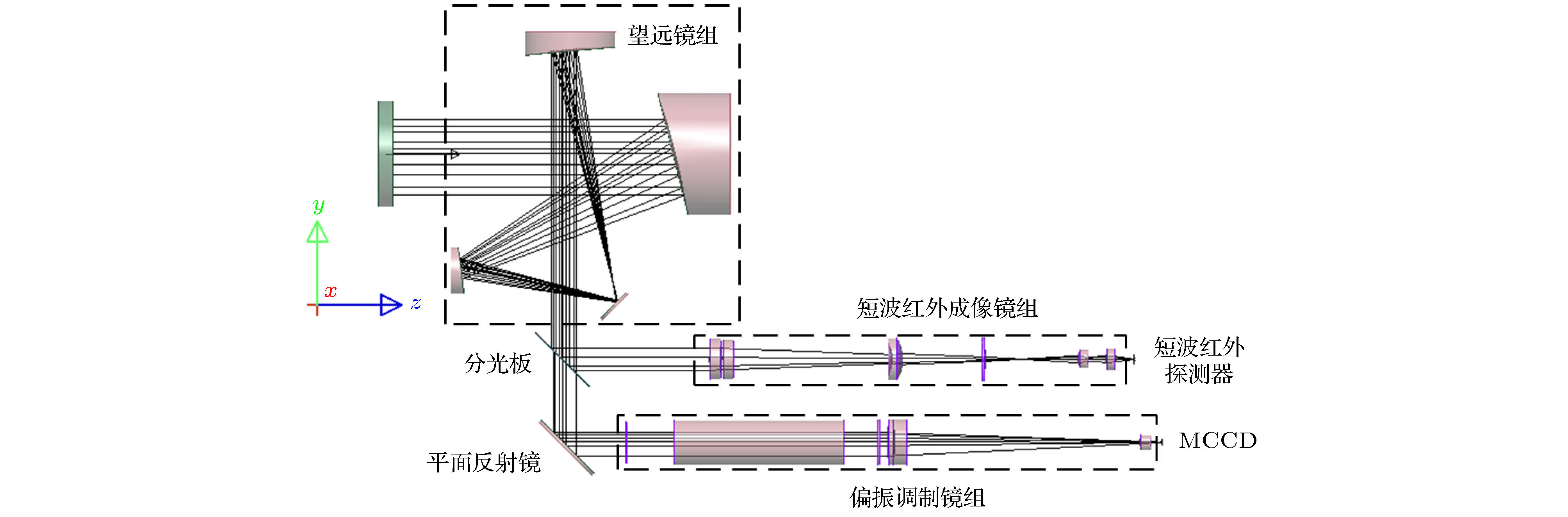
图 1 偏振成像激光雷达与短波红外复合光学系统成像原理图
Fig. 1. Schematic diagram of the polarization imaging lidar and short-wave infrared composite optical system.
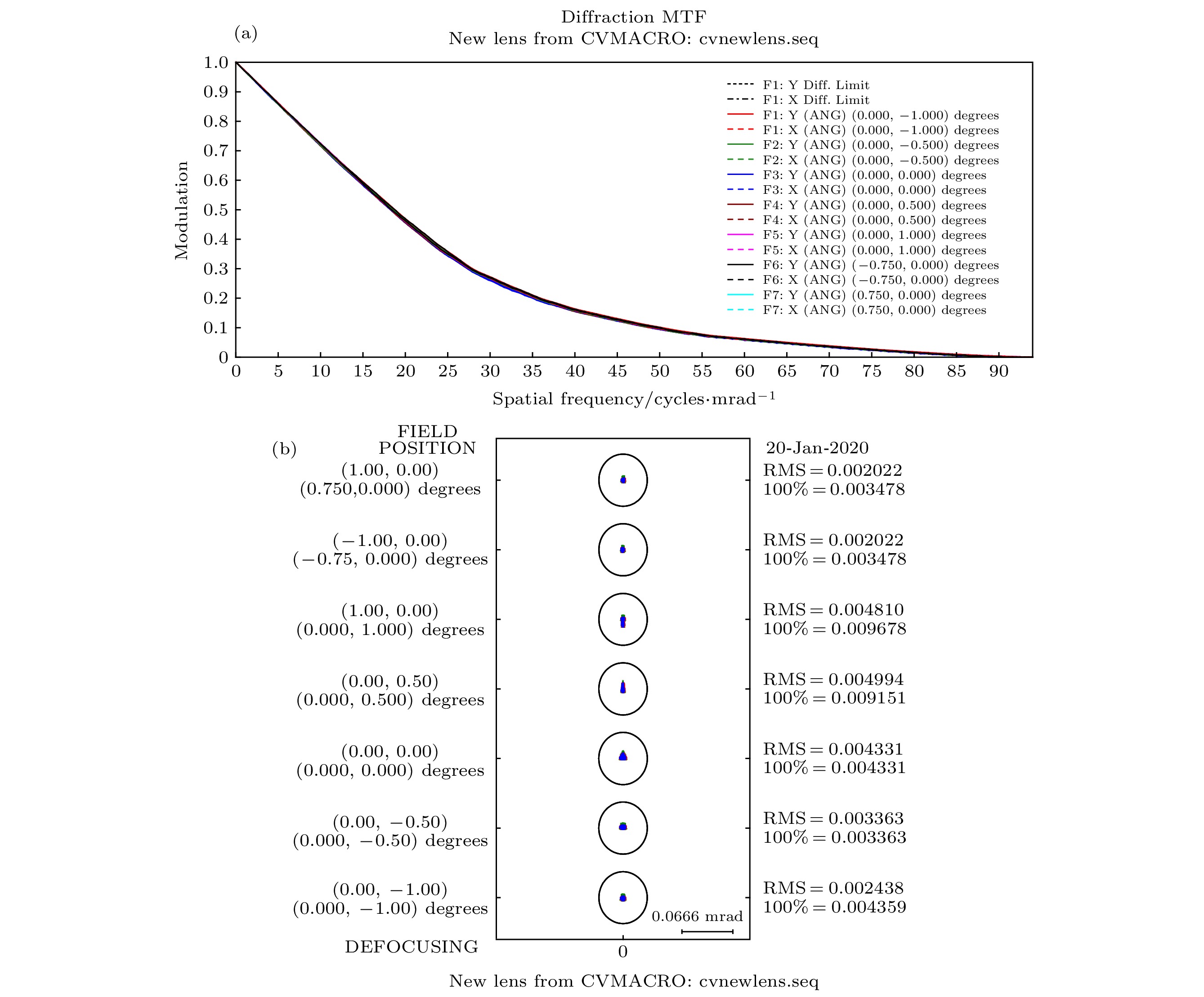
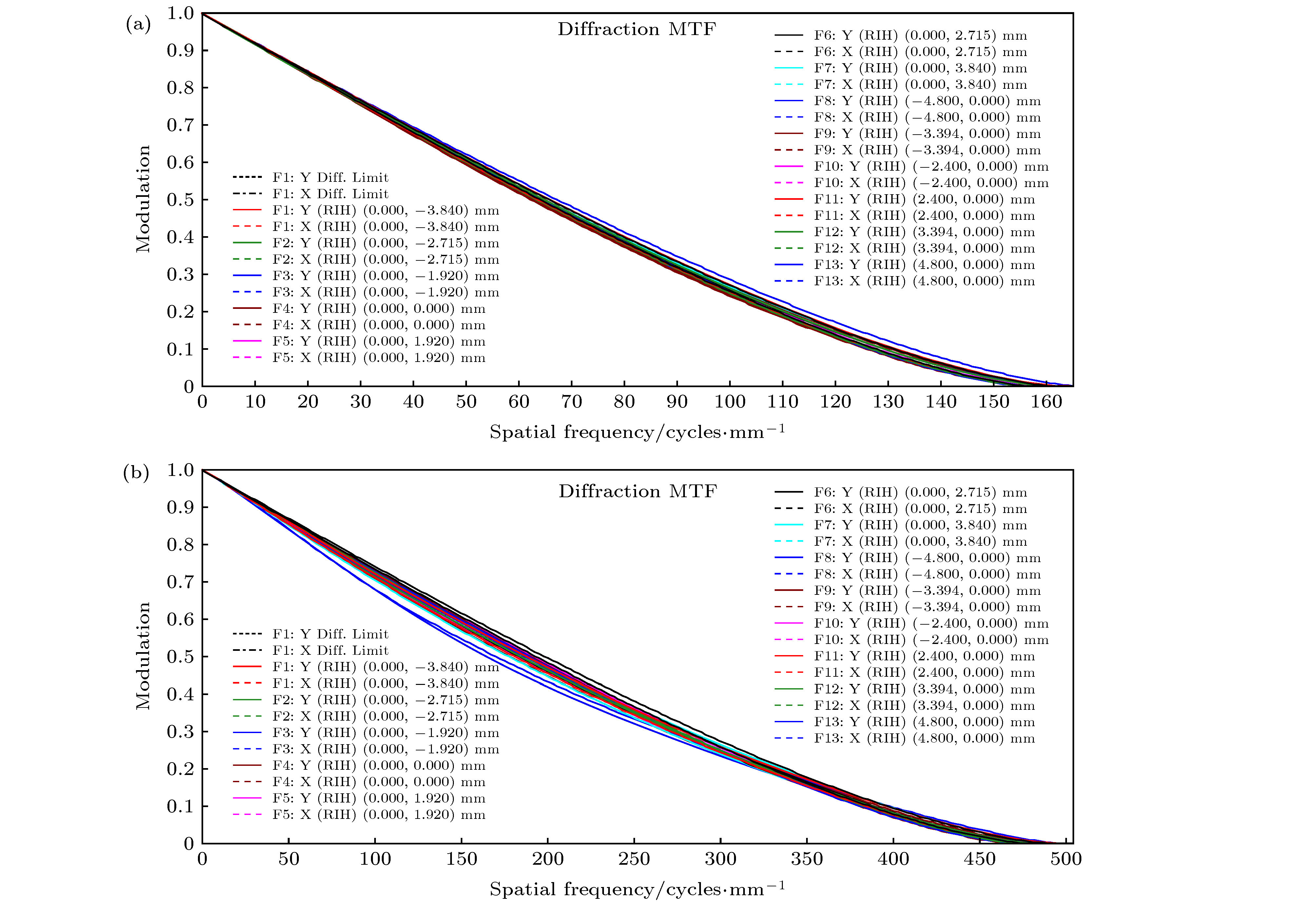
图 3 接收光学系统像质分析图 (a) MTF图; (b)点列图
Fig. 3. Image quality analysis diagram of the receiving optical system: (a) MTF diagram; (b) point column diagram.
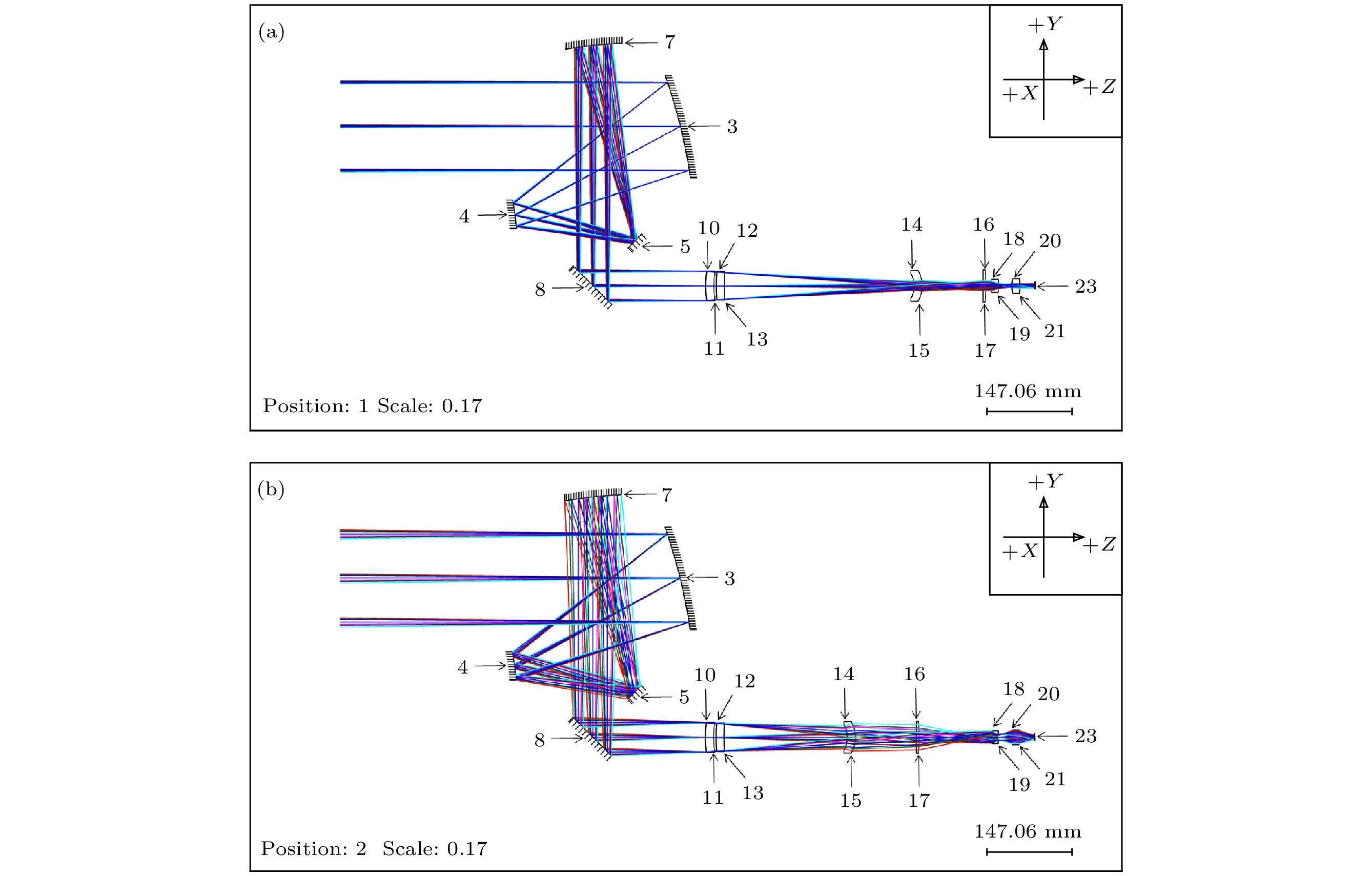
图 4 短波红外成像镜组光路图 (a)长焦模式, 焦距为900 mm; (b)短焦模式, 焦距为300 mm
Fig. 4. Optical path figure of the short wave infrared imaging lens: (a) Long-focus mode (the focal length is 900 mm); (b) short-focus mode (the focal length is 300 mm).
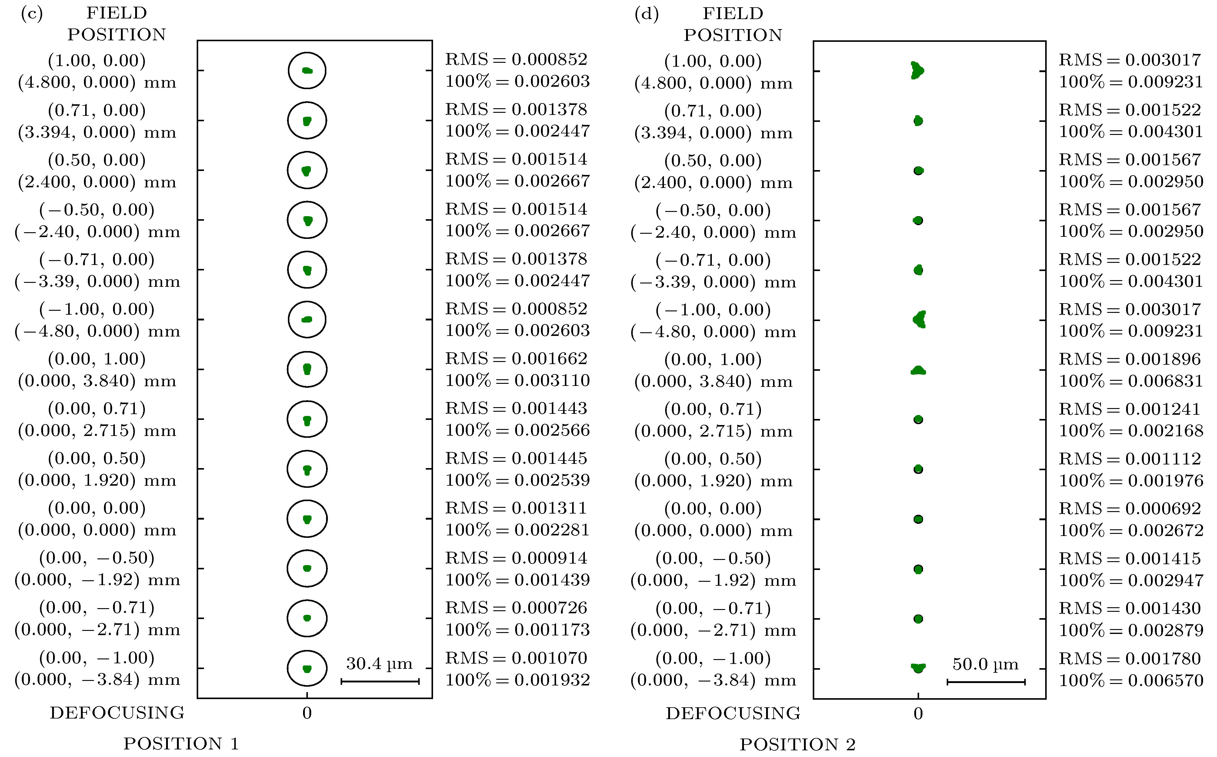
图 5 短波红外成像镜组像质分析图 (a)长焦模式MTF图; (b)短焦模式MTF图; (c)长焦模式点列图; (d)短焦模式点列图
Fig. 5. Image quality analysis diagram of the short wave infrared imaging lens: (a) MTF diagram of the long-focus mode; (b) MTF diagram of the short-focus mode; (c) point column diagram of the long-focus mode; (d) point column diagram of the short-focus mode

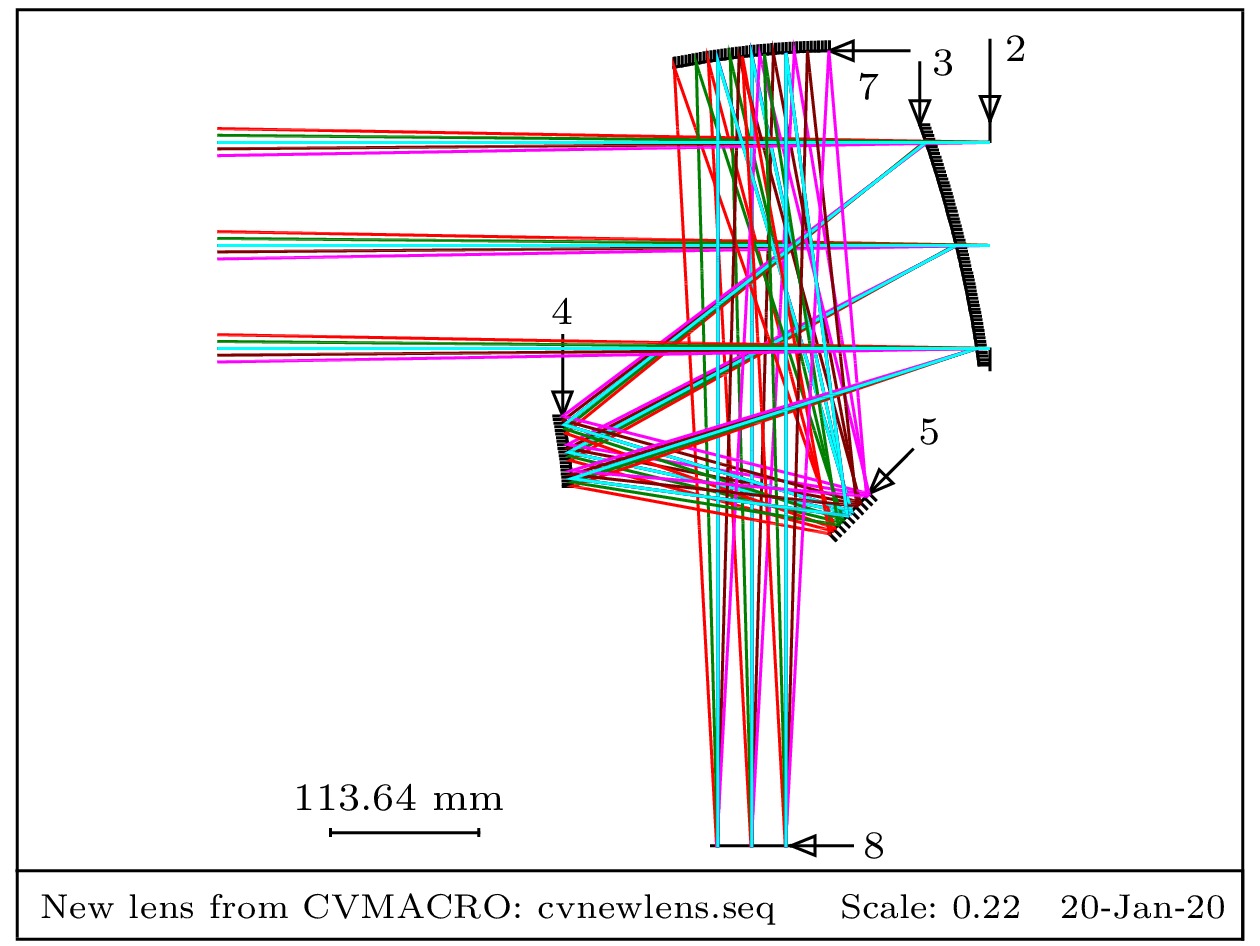
图 7 杂散光条件下15 km处目标成像仿真光路及目标光源图
Fig. 7. Target imaging simulation optical path and target light source diagram at 15 km under stray light condition.

图 9 成像照度分析图 (a)短波红外短焦模式; (b)短波红外长焦模式; (c)偏振成像激光雷达
Fig. 9. Analysis diagram of the imaging illuminance: (a) Short-wave infrared short-focus mode; (b) short-wave infrared long-focus mode; (c) polarization imaging lidar.
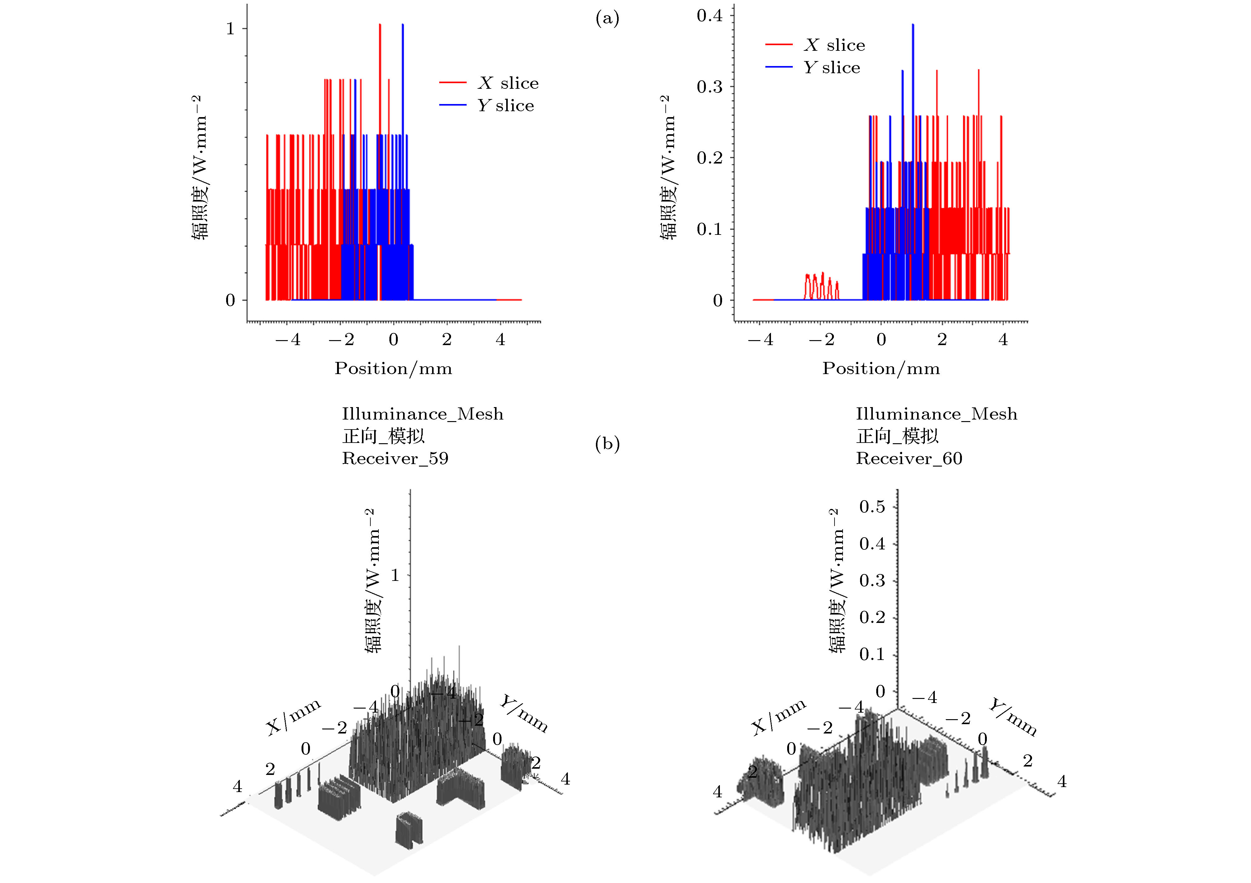
图 10 偏振成像激光雷达与短波红外长焦模式照度对比图 (a)成像表面照度; (b)三维照度对比图
Fig. 10. Contrast chart of the polarization imaging liDAR and short-wave infrared long-focus mode imaging: (a) Surface illumination; (b) three-dimensional illumination.
表 1 复合系统参数指标
Table 1. Parameter of the composite system.
参数 短波红外变焦成像 偏振成像激光雷达 工作波段 0.9—1.7 μm 0.532 μm 探测器像元尺寸 15 μm 3.45 μm 探测器像元数 640 × 512 2448 × 2048 焦距 300(900) mm 725 mm 视场角 2° × 1.5° (0.67° × 0.5°) 0.67° × 0.56° 入瞳直径 150 mm 150 mm F数 2(6) 4.8 MTFdesign ≥ 0.408 ≥ 0.408  下载: 导出CSV
表 2 光学系统公差值
Table 2. Tolerance value of the optical system.
公差项 短波红外成
像镜组偏振调
制镜组曲率半径公差最小值/mm 0.01 0.1 厚度公差最小值/mm 0.01 0.5 表面不规则度公差最
小值/ring0.5 0.5 空气间隔公差最小值/mm 0.04 0.08 装调偏心公差最小值/mm 0.01 0.02 装调倾斜公差最小值/mrad 0.15 0.15 折射率公差最小值 0.002 0.001
下载: 导出CSV
-
[1] 严惠民, 倪旭翔, 陈奇霖, 陆祖康 2000 中国激光 27 861
Google Scholar
Yan H M, Ni X X, Chen Q L, Lu Z K 2000 Chin. J. Lasers 27 861
Google Scholar
[2] McManamon P F 2012 Opt. Eng. 51 060901
Google Scholar
[3] Molebny V, Steinvall O 2014 Proc. SPIE 9080 908002
[4] 刘博, 于洋, 姜朔 2019 光电工程 46 190167
Google Scholar
Li B, Yu Y, Jiang S 2019 Opto-Electronic Eng. 46 190167
Google Scholar
[5] 曹秋生 2016 红外与激光工程 45 1003002
Google Scholar
Cao Q S 2016 Infrared Laser Eng. 45 1003002
Google Scholar
[6] 卜禹铭, 杜小平, 曾朝阳, 赵继广, 宋一铄 2018 中国光学 11 711
Google Scholar
Bu Y M, Du X P, Zeng C Y, Zhao J G, Song Y S 2018 Chin. OPT. 11 711
Google Scholar
[7] 姜凯 2013 博士学位论文 (西安: 中国科学院西安光学精密机械研究所)
Jiang K 2013 Ph. D. Dissertation (Xi'an: Xi'an Institute of Optics and Precision Mechanics, Chinese Academy of Sciences) (in Chinese)
[8] 李荣刚, 张兴德, 孙昌锋, 刘琳, 李江勇, 王诚 2013 激光与红外 43 128
Li R G, Zhang X D, Sun C F, Liu L, Li J Y, Wang C 2013 Laser Infrared 43 128
[9] 贾冰, 曹国华, 吕琼莹, 丁红昌 2016 红外与激光工程 46 218001
Google Scholar
Jia B, Cao G H, Lv Q Y, Ding H C 2016 Infrared Laser Eng. 46 218001
Google Scholar
[10] 丛海佳 2013 硕士学位论文 (哈尔滨: 哈尔滨工业大学)
Cong H J 2013 M.S. Thesis (Haerbin: Harbin Institute of Technology) (in Chinese)
[11] Jo S, Kong H J, Bang H 2016 Opt. Express. 24 A1580
Google Scholar
[12] Chen Z, Li B, Wang S J, Liu E H 2018 Appl. Opt. 57 7750
Google Scholar
[13] 陈臻 2017 博士学位论文 (成都: 中国科学院研究生院)
Chen Z 2017 Ph. D. Dissertation (Chengdu: Graduate School of Chinese Academy of Sciences) (in Chinese)
[14] 白廷柱, 金伟其 2015 光电成像原理与技术 (北京: 北京理工大学出版社) 第48−52页
Bai T Z, Jin W Q 2015 Opto-electric Imaging Technology (Beijing: Beijing Institute of Technology Press) pp48−52 (in Chinese)
[15] 邢振冲 2018 博士学位论文 (长春: 中国科学院长春光学精密机械与物理研究所)
Xing Z C 2018 Ph. D. Dissertation (Changchun: Changchun Institute of Optics, Fine Mechanics and Physics, Chinese Academy of Sciences) (in Chinese)
[16] 常军, 张晓芳, 张柯, 牛亚军 2017 现代反射变焦光学系统 (北京: 国防工业出版社) 第6−10页
Chang J, Zhang X F, Zhang K, Niu Y J 2017 Modern Reflective Zoom Optical System (Beijing: National Defence Industry Press) pp6−10 (in Chinese)
[17] 庞武斌, 岑兆丰, 李晓彤, 钱炜, 尚红波, 许伟才 2012 物理学报 61 234202
Google Scholar
Pang W B, Chen Z F, Li X T, Qian W, Shang H B, Xu W C 2012 Acta Phys. Sin. 61 234202
Google Scholar
[18] 李林, 黄一帆, 王涌天 2015 现代光学设计方法 (北京: 北京理工大学出版社) 第61−65页
Li L, Huang Y F, Wang Y T 2015 Modern Methods of Optical Design (Beijing: Beijing Institute of Technology Press) pp61−65 (in Chinese)
[19] 孟庆宇 2012 博士学位论文 (哈尔滨: 哈尔滨工业大学)
Meng Q Y 2012 Ph. D. Dissertation (Haerbin: Harbin Institute of Technology) (in Chinese)
[20] 殷玉龙, 孙晓兵, 宋茂新, 陈卫, 陈斐楠 2019 物理学报 68 024203
Google Scholar
Yin Y L, SunX B, Song M X, Chen W, Chen F N 2019 Acta Phys. Sin. 68 024203
Google Scholar

 下载:
下载:


计量
- 文章访问数: 12384
- PDF下载量: 245
- 被引次数: 0
