


-
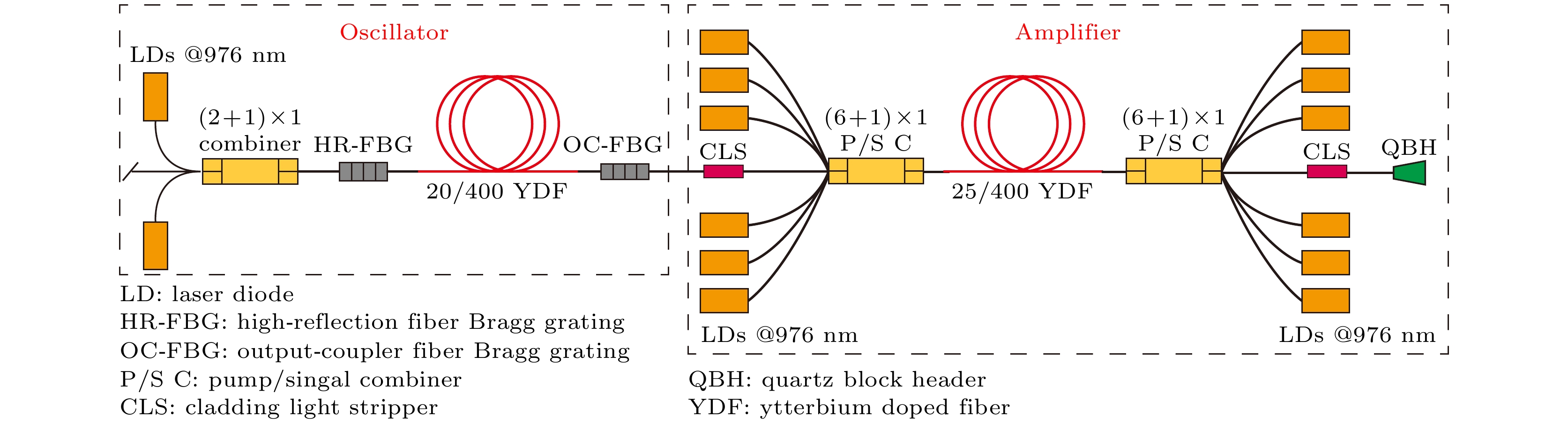
模式不稳定效应和非线性效应已经成为高功率光纤激光器中限制输出功率和光束质量进一步提升的主要障碍. 采用改进的化学气相沉积工艺结合溶液掺杂技术制备25/400 μm的M型掺镱双包层光纤, 纤芯和中间凹陷区域的数值孔径分别为0.054和0.025. 基于该光纤搭建976 nm双向泵浦全光纤结构放大器. 在泵浦光功率为3283 W时, 获得2285 W中心波长为1080 nm的激光输出, 3 dB线宽为3.01 nm, 测量的光束质量因子为1.42, 且未出现受激拉曼散射现象. 这是目前基于M型掺镱光纤实现的最高输出功率, 通过优化光纤结构参数实现功率进一步提升是有希望的.High power fiber laser systems have attracted extensive attention due to compactness, good beam quality, efficient heat dissipation and high conversion efficiency. They are widely used in industrial processing, military, medical treatment and other fields. Over the past two decades, owing to the development of double cladding fiber and high-brightness laser diodes, the output power of fiber lasers has been greatly improved. Unfortunately, nonlinear effects (NLEs), such as stimulated Brillouin scattering (SBS) and stimulated Raman scattering (SRS), restrict the further enhancement of the output power of fiber lasers. Apparently, increasing the core diameter is the most common way to suppress NLEs in the fiber, but this causes another limiting factor, i.e. mode instability (MI), resulting in the deterioration of the beam quality and in the limitation of the power scaling. Therefore, it is important and urgent to suppress the NLEs and MI simultaneously in fiber lasers. The M-type fiber, by designing refractive index profile, breaks through the stringent trade-off between mode area and numerical aperture (NA), so it possesses a larger mode area than the step index fiber, which helps to avoid NLEs and expand the power range. The M-type ytterbium doped double-clad fiber is fabricated by the modified chemical vapor deposition (MCVD) process with solution doping technology (SDT), the core/cladding diameter is 25/400 μm. The NA of high index ring and index dip in the core are 0.054 and 0.025, respectively. To test the performance of the M-type fiber during high-power operation, a 976 nm bidirectional pumped all-fiber amplifier is constructed. As a result, maximum output power of 2285 W is achieved with an optical-to-optical conversion efficiency of 66.5% under bidirectional pumping scheme, and the measured M 2 factor is 1.42, the central wavelength and 3 dB linewidth of output laser are 1080 nm and 3.01 nm, respectively. To the best of our knowledge, this is the highest output power in a continuous-wave fiber laser employing an M-type fiber at present. However, the MI effect is observed at the output power of 2252 W. The future work will focus on optimizing the structure of the M-type fiber to achieve a stabler higher-power and higher-efficiency laser output.
-
Keywords:
- M-type fiber /
- mode instability /
- fiber amplifier
[1] Jauregui C, Limpert J, Tünnermann A 2013 Nat. Photonics 7 861
 Google Scholar
[2] 王泽晖, 肖起榕, 王雪娇, 衣永青, 庞璐 2018 物理学报 67 024205
Google Scholar
Wang Z H, Xiao Q R, Wang X J, Yi Y Q, Pang L 2018 Acta Phys. Sin. 67 024205
Google Scholar
[3] 奚小明, 王鹏, 杨保来, 王小林, 张汉伟, 宁禹, 韩凯, 王泽锋, 周朴, 许晓军, 陈金宝 2021 中国激光 48 0116001
Google Scholar
Xi X M, Wang P, Yang B L, Wang X L, Zhang H W, Ning Y, Han K, Wang Z F, Zhou P, Xu X J, Chen J B 2021 Chin. J. Lasers 48 0116001
Google Scholar
[4] O’Connor M, Gapontsev V, Fomin V, Abramov M, Ferin A 2009 Conference on Lasers and Electro-Optics (CLEO) Baltimore, Maryland, USA, May 31–June 5, 2009 pCThA3
[5] [6] Wang Y, Kitahara R, Kiyoyama W, Shirakura Y, Kurihara T, Nakanish Y, Yamamoto T, Nakayama M, Ikoma S, Shima K 2020 Fiber Lasers XVII: Technology and Systems San Francisco, California, USA, February 2–21, 2020 p1126022
[7] Zervas M N, Codemard C A 2014 IEEE J. Sel. Top. Quantum Electron. 20 219
Google Scholar
[8] 陶汝茂, 周朴, 王小林, 司磊, 刘泽金 2014 物理学报 63 085202
Google Scholar
Tao R M, Zhou P, Wang X L, Si L, Liu Z J 2014 Acta Phys. Sin. 63 085202
Google Scholar
[9] Zervas M N 2019 Opt. Express 27 19019
Google Scholar
[10] Jain D, Jung Y, Barua P, Alam S, Sahu J K 2015 Opt. Express 23 7407
Google Scholar
[11] Ma X, Zhu C, Hu I N, Kaplan A, Galvanauskas A 2014 Opt. Express 22 9206
Google Scholar
[12] Wang M, Wang F, Feng S, Yu C, Wang S, Zhou Q, Zhang L, Lou F, Chen D, Hu L 2019 Chin. Opt. Lett. 17 71401
Google Scholar
[13] Stutzki F, Jansen F, Otto H J, Jauregui C, Limpert J, Tünnermann A 2014 Optica 1 233
Google Scholar
[14] 张志伦, 张芳芳, 林贤峰, 王世杰, 曹驰, 邢颍滨, 廖雷, 李进延 2020 物理学报 69 234205
Google Scholar
Zhang Z L, Zhang F F, Lin X F, Wang S J, Cao C, Xing Y B, Liao L, Li J Y 2020 Acta Phys. Sin. 69 234205
Google Scholar
[15] Jain D, George M A, Harris B, Fleming S 2021 J. Lightwave Technol. 39 4478
Google Scholar
[16] Glas P, Naumann M, Schirrmacher A, Unger S, Pertsch T 1998 Appl. Opt. 37 8434
Google Scholar
[17] Aleshkina S S, Likhachev M E, Senatorov A K, Bubnov M M, Salaganskii M Y, Guryanov A N 2013 Opt. Express 21 23838
Google Scholar
[18] Aleshkina S S, Yatsenko Y P, Salganskii M Y, Lipatov D S, Senatorov A K, Tausenev A V, Shepelev D V, Bubnov M M, Guryanov A N, Likhachev M E 2019 IEEE Photonics J. 11 1
Google Scholar
[19] Ghatak A K, Goyal I C, Jindal R 1999 International Conference on Fiber Optics and Photonics: Selected Papers from Photonics India’98 New Delhi, India, April 28, 1999 p40
[20] Wang C C, Zhang F, Lu Y C, Liu C, Geng R, Ning T G, and Jian S S 2009 J. Opt. A:Pure Appl. Opt. 11 65402
Google Scholar
[21] Valentin C, Calvet P, Quiquempois Y, Bouwmans G, Bigot L, Coulombier Q, Douay M, Delplace K, Mussot A, Hugonnot E 2013 Opt. Express 21 23250
Google Scholar
[22] Jain D, Sahu J K, Fleming S 2020 J. Lightwave Technol. 38 6362
Google Scholar
[23] Liu Y, Zhang F, Zhao N, Lin X, Liao L, Wang Y, Peng J, Li H, Yang L, Dai N, Li J 2018 Opt. Express 26 3421
Google Scholar
[24] Jain D, Baskiotis C, Sahu J K 2013 Opt. Express 21 26663
Google Scholar
[25] Wang X, Lou S, Lu W 2014 IEEE J. Sel. Top. Quantum Electron. 20 200
Google Scholar
[26] Wang X, Lou S, Lu W, Sheng X, Zhao T, Hua P 2016 IEEE J. Sel. Top. Quantum Electron. 22 117
Google Scholar
[27] Saitoh K, Tsuchida Y, Rosa L, Koshiba M, Poli F, Cucinotta A, Selleri S, Pal M, Paul M, Ghosh D, Bhadra S 2009 Opt. Express 17 4913
Google Scholar
[28] Shi C, Su R T, Zhang H W, Yang B L, Wang X L, Zhou P, Xu X J, Lu Q S 2017 IEEE Photonics J. 9 1
Google Scholar
-

图 1 M型光纤的折射率剖面; 插图为M型光纤的端面
Fig. 1. Refractive index profile of the M-type fiber. Inset is the end facet of an M-type fiber.
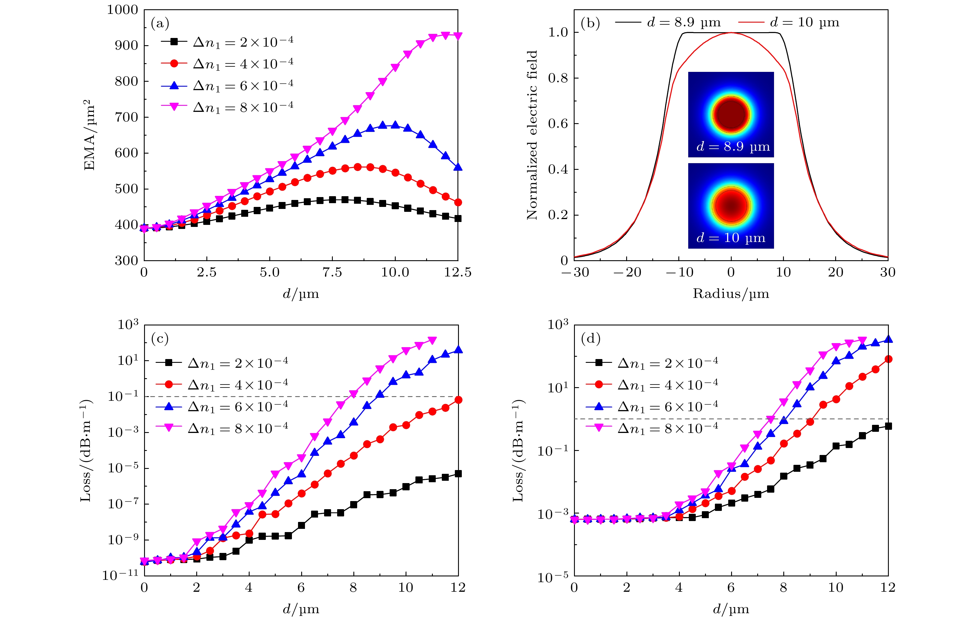
图 2 (a) 不同纤芯中间凹陷的深度(Δn1)及宽度(d)下基模的有效模场面积; (b) 当Δn1 = 6 × 10⁻⁴时, d = 8.9和10 μm的基模归一化电场(插图为相应的电场横向分量表面轮廓); 在弯曲直径30 cm下, 不同的Δn1及d下(c) LP01和(d) LP11的弯曲损耗
Fig. 2. (a) EMA of FM for different depth (Δn1) and width (d) of central dip in core; (b) when Δn1 = 6 × 10⁻⁴, normalized electric field of FM for d = 8.9 and 10 μm (Insets are the corresponding surface profiles of the transverse component of the electric fields); the bending losses of (c) LP01 and (d) LP11 for different Δn1 and d under a bending diameter of 30 cm.

图 3 (a) 光纤预制棒折射率剖面; (b) 光纤折射率剖面; (c) 纤芯区域元素分布; (d) LP01和LP11模式的弯曲损耗及LP01模式的有效模场面积随弯曲直径变化关系(插图为LP01和LP11模式在弯曲下的模场分布)
Fig. 3. (a) Refractive index profile of the fiber preform; (b) refractive index profile of the fiber; (c) elemental distribution in fiber core region; (d) the bending loss of LP01 and LP11 modes and the EMA of LP01 mode as a function of the bending diameter (Insets are mode filed distributions of LP01 and LP11 modes under bending).
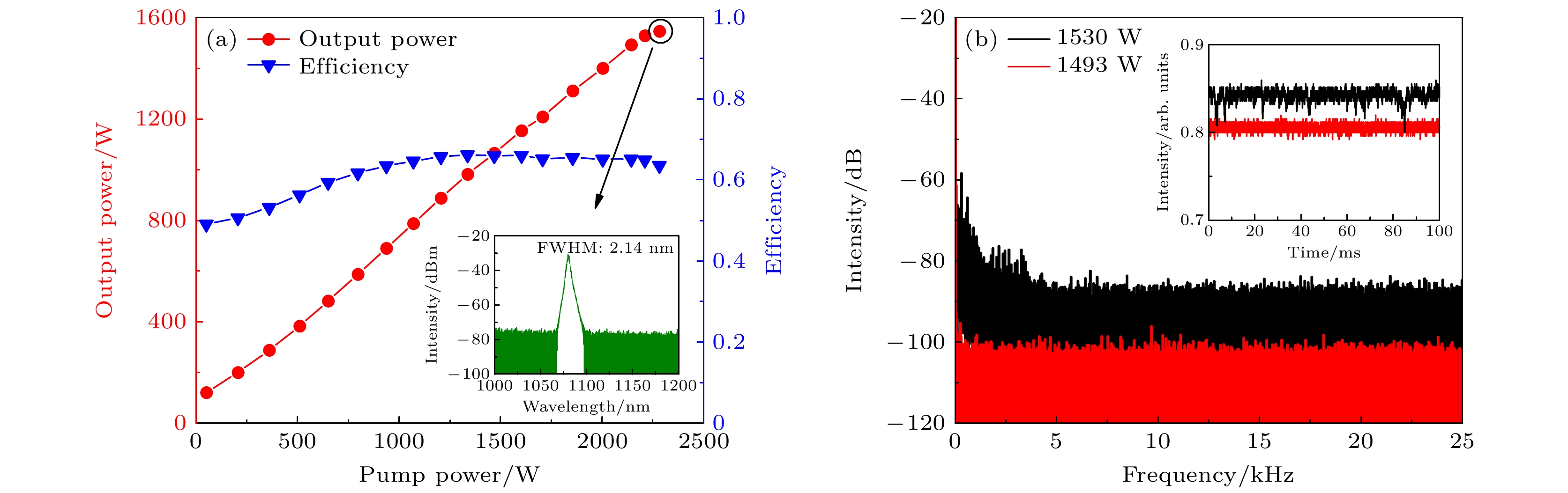
图 5 前向泵浦的实验结果 (a) 不同泵浦功率下的输出功率和效率(插图为最高输出功率下的光谱); (b) 不同输出功率下的时域信号(插图)及对应的频域信号
Fig. 5. Experimental results of forward-pumping: (a) Output power and efficiency at different pump powers (Inset is spectrum at the highest power); (b) time domain signal (inset) and corresponding frequency domain signal at different output powers.
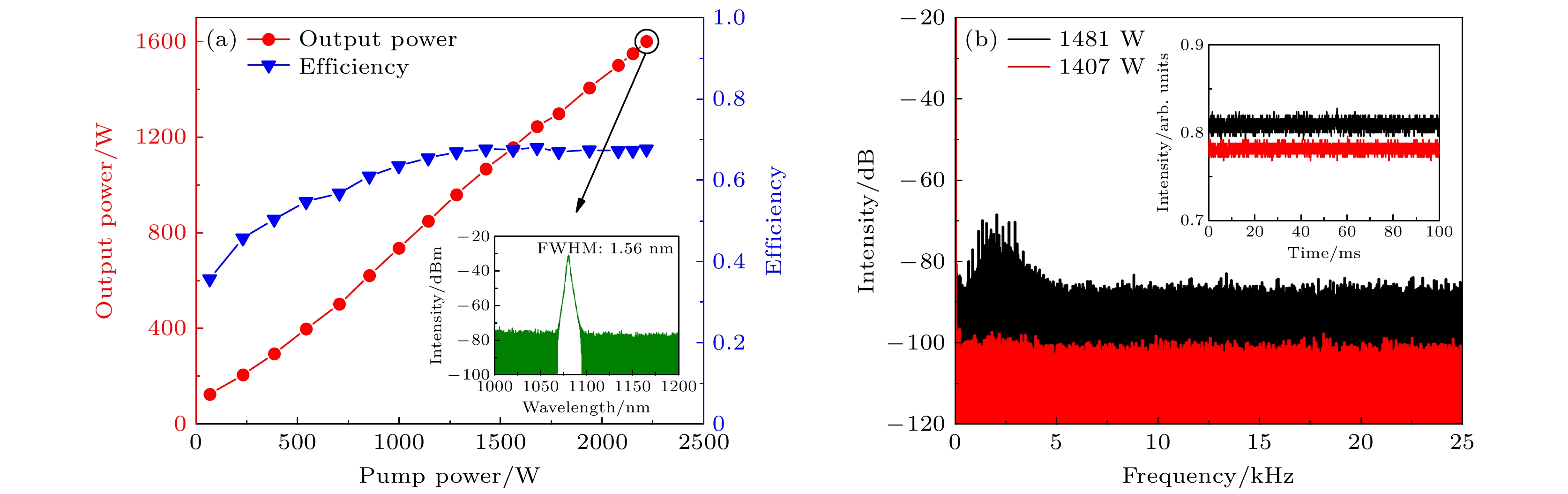
图 6 后向泵浦的实验结果 (a) 不同泵浦功率下的输出功率和效率(插图是最高输出功率下的光谱); (b) 不同输出功率下的时域信号(插图)及对应的频域信号
Fig. 6. Experimental results of backward-pumping: (a) Output power and efficiency at different pump powers (Inset is spectrum at the highest power); (b) time domain signal (inset) and corresponding frequency domain signal at different output powers.
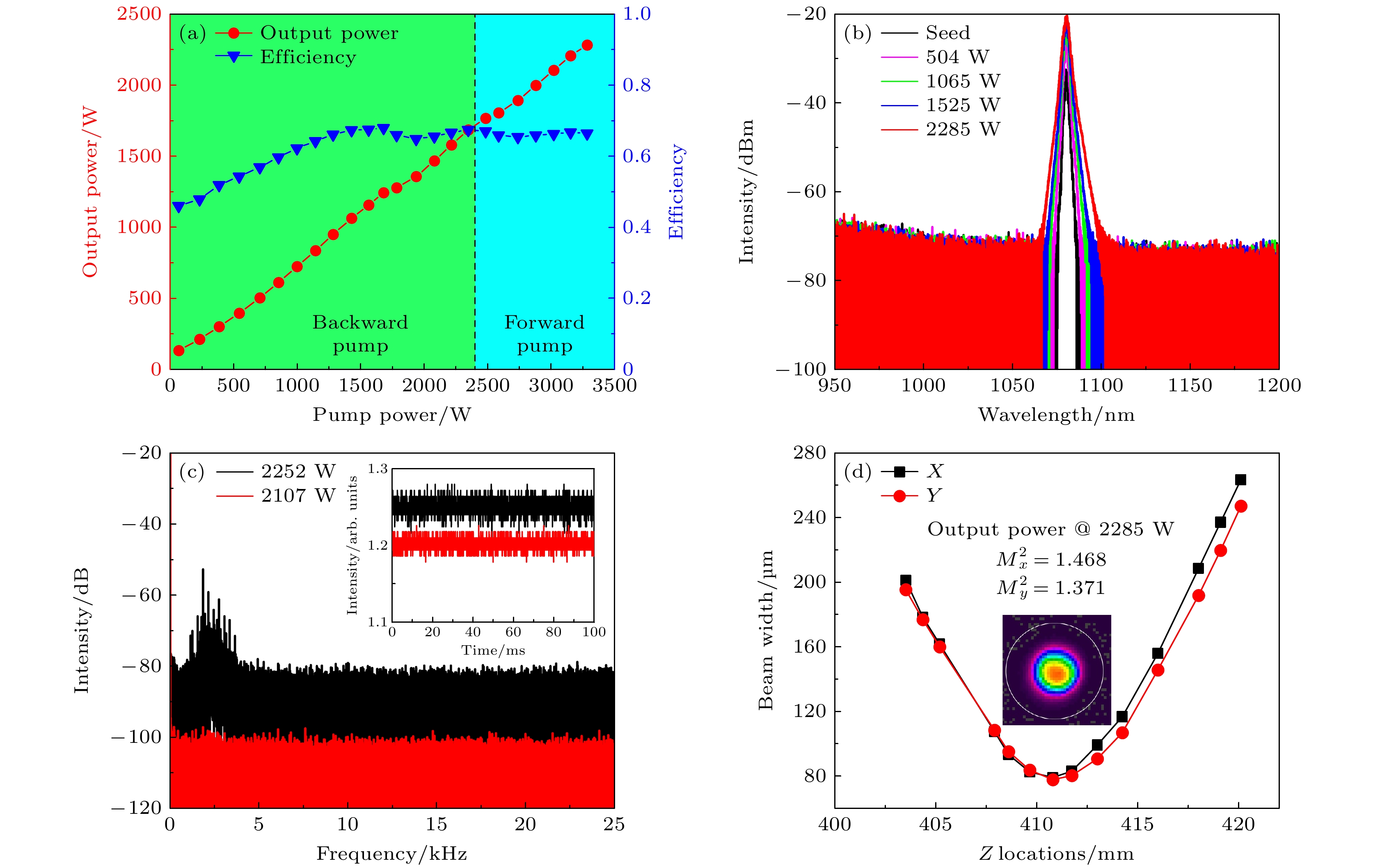
图 7 双向泵浦的实验结果 (a) 不同泵浦功率下的输出功率和效率; (b) 不同输出功率下测量的光谱; (c) 不同输出功率下的时域信号(插图)及对应的频域信号; (d) 最高输出功率时的激光光束质量
Fig. 7. Experimental results of bidirectional pumping: (a) Output power and efficiency at different pump powers; (b) measured spectra at different output powers; (c) time domain signal (inset) and corresponding frequency domain signal at different output powers; (d) the laser beam quality at the maximum output power.
-
[1] Jauregui C, Limpert J, Tünnermann A 2013 Nat. Photonics 7 861
Google Scholar
[2] 王泽晖, 肖起榕, 王雪娇, 衣永青, 庞璐 2018 物理学报 67 024205
Google Scholar
Wang Z H, Xiao Q R, Wang X J, Yi Y Q, Pang L 2018 Acta Phys. Sin. 67 024205
Google Scholar
[3] 奚小明, 王鹏, 杨保来, 王小林, 张汉伟, 宁禹, 韩凯, 王泽锋, 周朴, 许晓军, 陈金宝 2021 中国激光 48 0116001
Google Scholar
Xi X M, Wang P, Yang B L, Wang X L, Zhang H W, Ning Y, Han K, Wang Z F, Zhou P, Xu X J, Chen J B 2021 Chin. J. Lasers 48 0116001
Google Scholar
[4] O’Connor M, Gapontsev V, Fomin V, Abramov M, Ferin A 2009 Conference on Lasers and Electro-Optics (CLEO) Baltimore, Maryland, USA, May 31–June 5, 2009 pCThA3
[5] [6] Wang Y, Kitahara R, Kiyoyama W, Shirakura Y, Kurihara T, Nakanish Y, Yamamoto T, Nakayama M, Ikoma S, Shima K 2020 Fiber Lasers XVII: Technology and Systems San Francisco, California, USA, February 2–21, 2020 p1126022
[7] Zervas M N, Codemard C A 2014 IEEE J. Sel. Top. Quantum Electron. 20 219
Google Scholar
[8] 陶汝茂, 周朴, 王小林, 司磊, 刘泽金 2014 物理学报 63 085202
Google Scholar
Tao R M, Zhou P, Wang X L, Si L, Liu Z J 2014 Acta Phys. Sin. 63 085202
Google Scholar
[9] Zervas M N 2019 Opt. Express 27 19019
Google Scholar
[10] Jain D, Jung Y, Barua P, Alam S, Sahu J K 2015 Opt. Express 23 7407
Google Scholar
[11] Ma X, Zhu C, Hu I N, Kaplan A, Galvanauskas A 2014 Opt. Express 22 9206
Google Scholar
[12] Wang M, Wang F, Feng S, Yu C, Wang S, Zhou Q, Zhang L, Lou F, Chen D, Hu L 2019 Chin. Opt. Lett. 17 71401
Google Scholar
[13] Stutzki F, Jansen F, Otto H J, Jauregui C, Limpert J, Tünnermann A 2014 Optica 1 233
Google Scholar
[14] 张志伦, 张芳芳, 林贤峰, 王世杰, 曹驰, 邢颍滨, 廖雷, 李进延 2020 物理学报 69 234205
Google Scholar
Zhang Z L, Zhang F F, Lin X F, Wang S J, Cao C, Xing Y B, Liao L, Li J Y 2020 Acta Phys. Sin. 69 234205
Google Scholar
[15] Jain D, George M A, Harris B, Fleming S 2021 J. Lightwave Technol. 39 4478
Google Scholar
[16] Glas P, Naumann M, Schirrmacher A, Unger S, Pertsch T 1998 Appl. Opt. 37 8434
Google Scholar
[17] Aleshkina S S, Likhachev M E, Senatorov A K, Bubnov M M, Salaganskii M Y, Guryanov A N 2013 Opt. Express 21 23838
Google Scholar
[18] Aleshkina S S, Yatsenko Y P, Salganskii M Y, Lipatov D S, Senatorov A K, Tausenev A V, Shepelev D V, Bubnov M M, Guryanov A N, Likhachev M E 2019 IEEE Photonics J. 11 1
Google Scholar
[19] Ghatak A K, Goyal I C, Jindal R 1999 International Conference on Fiber Optics and Photonics: Selected Papers from Photonics India’98 New Delhi, India, April 28, 1999 p40
[20] Wang C C, Zhang F, Lu Y C, Liu C, Geng R, Ning T G, and Jian S S 2009 J. Opt. A:Pure Appl. Opt. 11 65402
Google Scholar
[21] Valentin C, Calvet P, Quiquempois Y, Bouwmans G, Bigot L, Coulombier Q, Douay M, Delplace K, Mussot A, Hugonnot E 2013 Opt. Express 21 23250
Google Scholar
[22] Jain D, Sahu J K, Fleming S 2020 J. Lightwave Technol. 38 6362
Google Scholar
[23] Liu Y, Zhang F, Zhao N, Lin X, Liao L, Wang Y, Peng J, Li H, Yang L, Dai N, Li J 2018 Opt. Express 26 3421
Google Scholar
[24] Jain D, Baskiotis C, Sahu J K 2013 Opt. Express 21 26663
Google Scholar
[25] Wang X, Lou S, Lu W 2014 IEEE J. Sel. Top. Quantum Electron. 20 200
Google Scholar
[26] Wang X, Lou S, Lu W, Sheng X, Zhao T, Hua P 2016 IEEE J. Sel. Top. Quantum Electron. 22 117
Google Scholar
[27] Saitoh K, Tsuchida Y, Rosa L, Koshiba M, Poli F, Cucinotta A, Selleri S, Pal M, Paul M, Ghosh D, Bhadra S 2009 Opt. Express 17 4913
Google Scholar
[28] Shi C, Su R T, Zhang H W, Yang B L, Wang X L, Zhou P, Xu X J, Lu Q S 2017 IEEE Photonics J. 9 1
Google Scholar

 下载:
下载:
计量
- 文章访问数: 6896
- PDF下载量: 127
- 被引次数: 0
