


-
利用VO2嵌入超表面设计了一种实现不同频率, 且线极化和圆极化两种模式入射下均产生高效率吸收的太赫兹超表面. 当VO2为绝缘态时, 设计的超表面对圆极化波的旋向产生选择性吸收, 在1.30 THz处对左旋圆极化波产生的吸收率大于95%, 对右旋圆极化波不吸收, 圆二色性为0.85. 当VO2为金属态时, 在1.95 THz处, 该超表面对TE线极化入射波吸收率达到98.5%. 结果表明, 在线极化和圆极化波入射下, 所设计的超表面结构具有良好的广角吸收性能. 由于它具有形态简单、易于加工等特点, 在太赫兹波传感、成像和通信领域具有广阔的应用前景.In recent years, the development of ultrafast laser technology has provided a stable and reliable terahertz source for generating terahertz wave pulses, and the great research progress of terahertz wave has been made. As a new type of two-dimensional artificial metamaterial, metasurface can effectively control the transmission, reflection and polarization of electromagnetic waves, which has attracted the extensive attention. Most of the reported terahertz absorbers so far are based on metasurfaces with linear polarization incidence, and few studies have been conducted on terahertz metasurfaces that can produce efficient absorption at both linear and circular polarization incidence, which limits the practical application areas. Therefore, it is necessary to explore an efficient absorber which can realize both linear polarization and circular polarization. We propose a vanadium dioxide composite metasurface structure. The vanadium dioxide is a typical temperature-controlled phase change material, and its conductivity will undergo a huge mutation in the phase change process. When the temperature is lower than the critical temperature (68 ℃), the vanadium dioxide has high resistivity and good insulation performance. When the temperature is higher than the critical temperature, the resistance changes from high resistance state to low resistance state, showing metal characteristics. By changing the external temperature, the phase of vanadium dioxide is changed, the free switching frequency is achieved and both the linear polarization and circular polarization incident efficient absorption are realized. When the vanadium dioxide is insulated, its conductivity is 0 S/m, the metasurface can absorb left-handed circularly polarized wave at 1.30 THz and reflect the incident right-handed circularly polarized wave, and the circular dichroism is 0.85. When the vanadium dioxide is metallic, its conductivity is 2×10⁵ S/m and it possesses linearly polarized incident metasurface, the absorption rate of TE linearly polarized incident wave by metasurface reaches 98.5% at 1.95 THz, and the perfect absorption of terahertz wave is realized. The structure has good wide-angle absorption performance for both TE polarization wave and left-handed circularly polarized wave. This composite metasurface structure can achieve the good absorption effect of terahertz waves with different frequencies and different polarization states. Therefore, the design concept of the composite metasurface structure can be used for designing other metasurface terahertz devices, and also for implementing the terahertz imaging and sensing systems due to different response characteristics to different polarization signals.
-
Keywords:
- terahertz composite metasurface /
- linearly polarized /
- circularly polarized /
- circular dichroism
[1] Chen L, Liao D G, Guo X G, Zhao J Y, Zhu Y M, Zhuang S L 2019 Front Inform. Technol. Electron. Eng. 20 591
 Google Scholar
[2] Xu B L, Zhong R B, Liang Z K, et al. 2022 Front Mater 9 881229
Google Scholar
[3] Zheng Z P, Luo Y, Yang H, et al. 2022 Phys. Chem. Chem. Phys. 24 8846
Google Scholar
[4] Zhang Y G, Qiu F, Liang L J, Yao H Y, Yan X, Liu W J, Huang C C, Yao J Q 2022 Opt. Express 30 24703
Google Scholar
[5] Tang B, Ren Y 2022 Phys. Chem. Chem. Phys. 24 8408
Google Scholar
[6] Luo H, Wang X, Qian H 2021 J. Opt. Soc. Am. B 38 2638
Google Scholar
[7] Aghili S, Amini A, Dizaj L S, Dolgaleva K 2022 Opt. Commun. 508 127805
Google Scholar
[8] Zhu L, Zhao X, Miao F J, Ghosh B K, Dong L, Tao B R, Meng F Y, Li W N 2019 Opt. Express 27 12163
Google Scholar
[9] Zhang Y D, Liu H Q, Xu R G, Qin Z J, Teng C X, Deng S J, Chen M, Cheng Y, Deng H C, Yang H Y, Qu S L, Yuan L B 2021 Opt. Express 29 21020
Google Scholar
[10] Wang X Y, Ma C, Xiao L H, et al. 2022 Appl. Opt. 61 1646
Google Scholar
[11] Li R, Pan M, Yi Z, Yu J X, Shi P C, Luo H, Wu P H, Yang H, Wang S F, Gao G C 2022 Opt. Laser Technol. 153 108284
Google Scholar
[12] Chen X Y, Tian Z, Lu Y C, Xu Y H, Zhang X Q, Ouyang C M, Gu J Q, Han J G, Zhang W L 2020 Adv. Optical Mater. 8 1900660
Google Scholar
[13] Hu N, Wu F L, Bian L A, Liu H Q, Liu P G 2018 Opt. Mater. Express 8 3899
Google Scholar
[14] 杨鹏 韩天成 2018 物理学报 67 107801
Google Scholar
Yang P, Han T C 2018 Acta Phys. Sin. 67 107801
Google Scholar
[15] Yan D X, Li J S 2019 Laser Phys. 29 046203
Google Scholar
[16] Divdel H, Taghipour-Farshi H, Saghai H R, Jahani M A T G 2020 Opt. Eng. 59 127108
Google Scholar
[17] Zhao Y, Zeng L, Zhang X L, Ye H N, Zhang H F 2021 J. Opt. 23 085102
Google Scholar
[18] Liang S, Zhu Z B, Jiang L Y 2022 Eng. Res. Express 4 035006
Google Scholar
[19] Li Z W, Li J S 2021 Appl. Opt. 60 2450
Google Scholar
[20] Mutlu M, Akosman A E, Serebryannikov A E, Ozbay E 2012 Phys. Rev. Lett. 108 213905
Google Scholar
[21] Wang T L, Zhang Y P, Zhang H Y, Cao M Y 2020 Opt. Mater. Express 10 369
Google Scholar
-
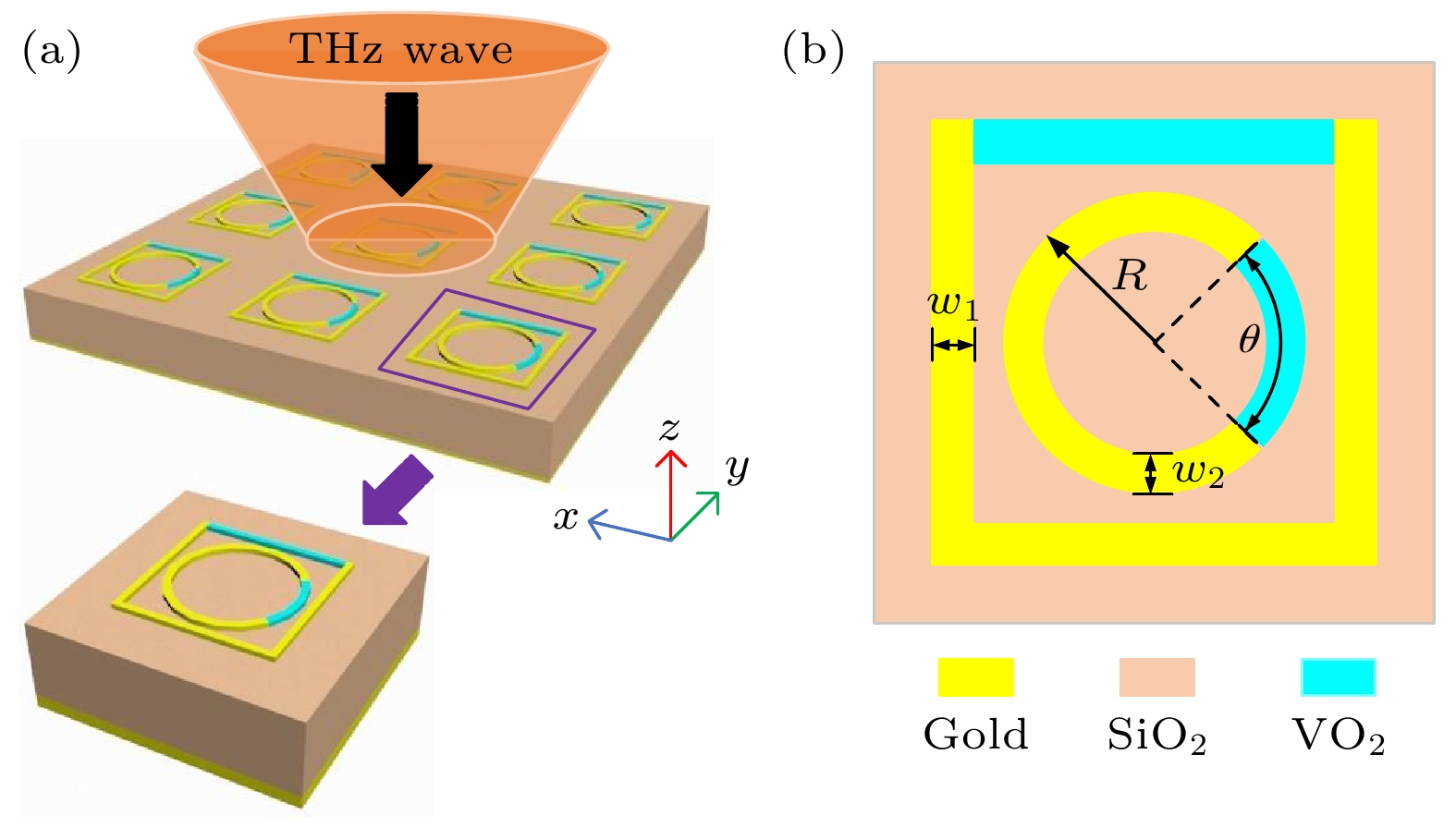
图 1 所设计的工作频率可切换, 对线极化和圆极化入射波均产生完美吸收的太赫兹吸收器结构示意图 (a) 三维结构图; (b) 单元俯视图
Fig. 1. Schematic diagram of the designed terahertz absorber with switchable operating frequency and perfect absorption for both linearly polarized and circularly polarized waves incidence: (a) 3D structure diagram; (b) top view of the unit.

图 2 LCP波和RCP波入射下所设计超表面结构的电磁响应曲线 (a)反射系数; (b)吸收率及圆二色性
Fig. 2. Electromagnetic response curves of the designed metasurface structures under the incident of LCP and RCP waves: (a) Reflection coefficient; (b) absorption and circular dichroism.
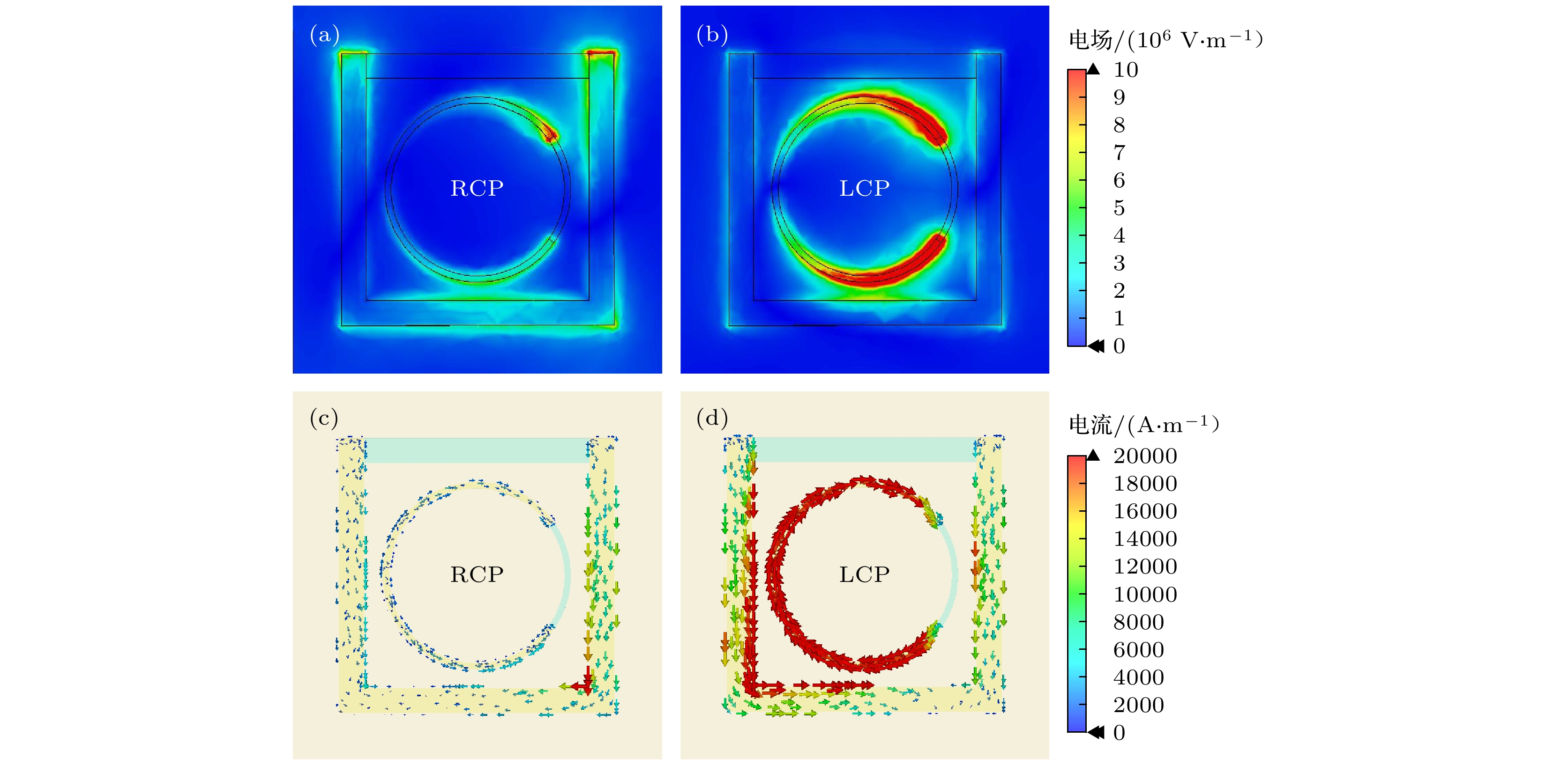
图 3 LCP和RCP太赫兹波入射下的电场分布图与电流分布图 (a) RCP入射下的电场分布; (b) LCP入射下的电场分布; (c) RCP入射下的电流分布; (d) LCP入射下的电流分布
Fig. 3. Electric field distribution diagram and current distribution diagram under the LCP and RCP waves incidence: (a) Electric field distribution under RCP incidence; (b) electric field distribution under LCP incidence; (c) current distribution under RCP incidence; (d) current distribution under LCP incidence.
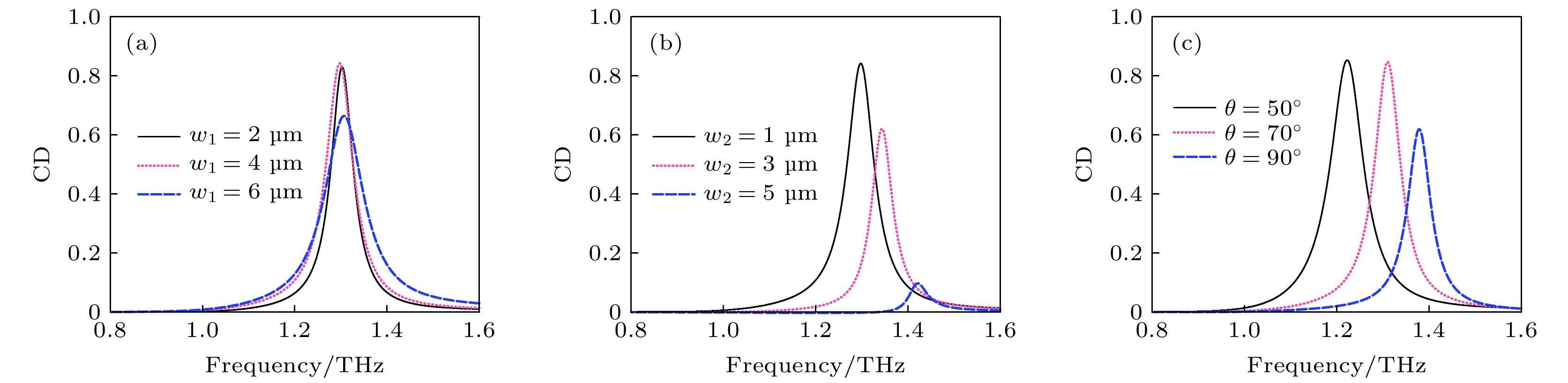
图 4 不同结构参数对所设计超表面的CD影响情况 (a) 线宽w1; (b) 线宽w2; (c) 间隙θ
Fig. 4. Influence of different structural parameters on the CD of the designed metasurface: (a) Line width w1; (b) line width w2; (c) angle θ
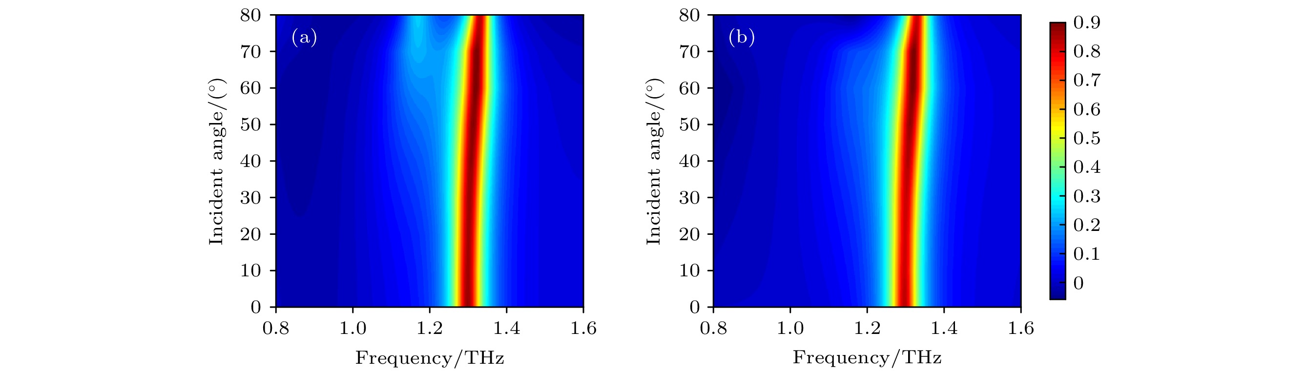
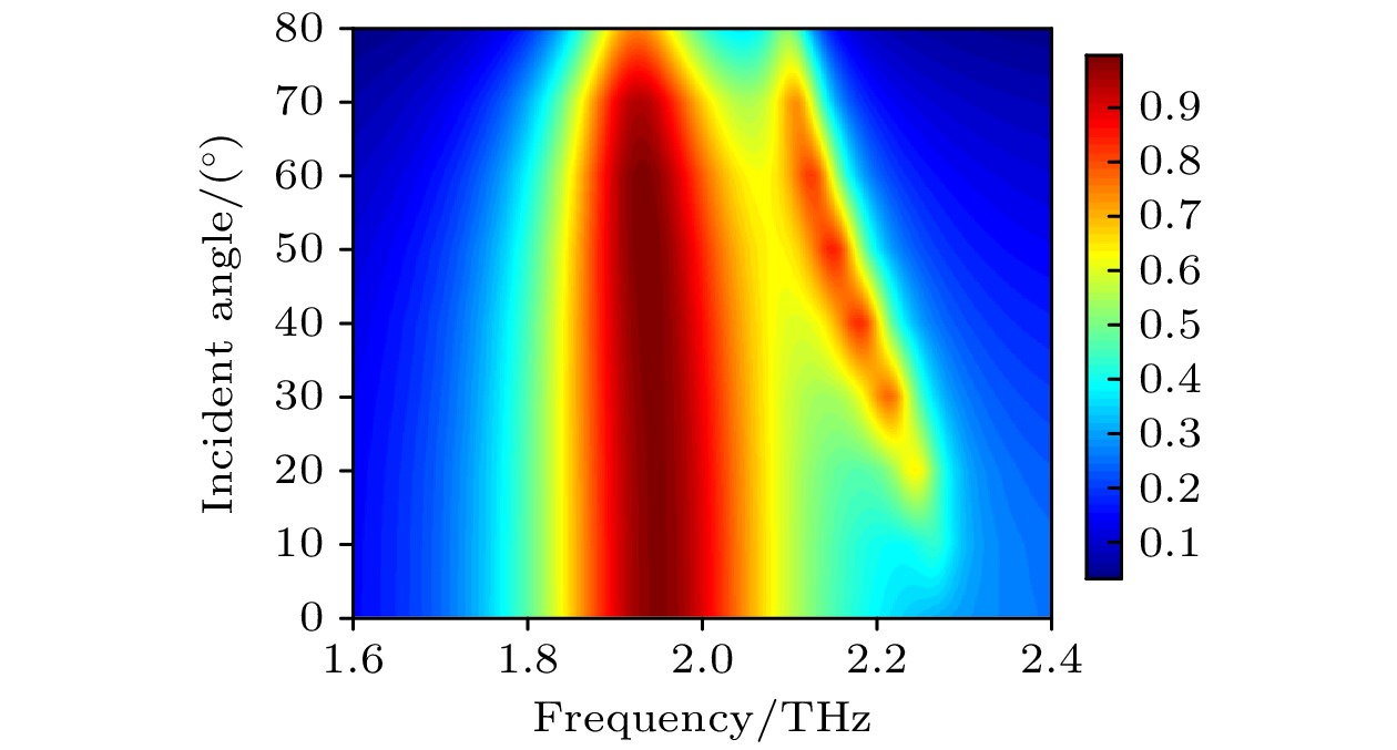
图 5 入射角对所设计超表面的吸收特性影响 (a) LCP; (b) CD
Fig. 5. Incident angle vs. absorption properties of the designed metasurface: (a) LCP; (b) CD.
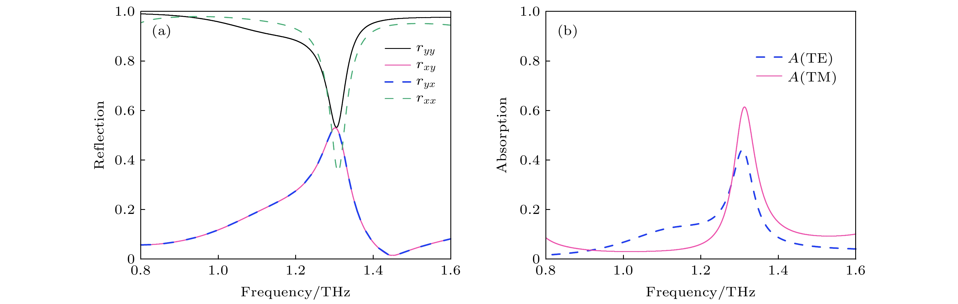
图 6 TE波和TM波入射下所设计结构的电磁响应曲线 (a) 反射系数; (b) 吸收率
Fig. 6. Electromagnetic response curves of the designed structures under the incident of TE and TM waves: (a) Reflection coefficient; (b) absorption.

图 7 LCP和RCP太赫兹波入射到所设计超表面结构产生的电磁响应曲线 (a) 反射系数; (b) 吸收率及圆二色性
Fig. 7. Electromagnetic response curves of the designed structures under LCP and RCP waves incidence: (a) Reflection coefficient; (b) absorption and circular dichroism.

图 8 TE和TM极化太赫兹波入射到复合超表面结构产生的电磁响应曲线 (a) 反射谱; (b) 吸收谱
Fig. 8. Electromagnetic response curves of TE and TM polarized terahertz wave is incident on the designed composite metasurface structure: (a) Reflection coefficient; (b) absorption coefficient.
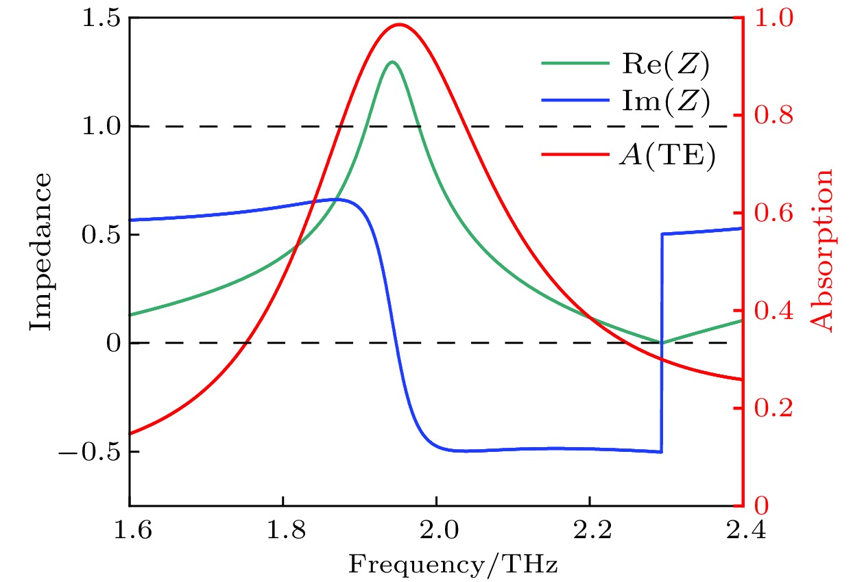
图 9 TE波入射到复合超表面结构产生的等效阻抗实部与虚部
Fig. 9. Real and imaginary parts of the equivalent impedance of the designed composite metasurface structure under the TE wave incidence.

图 10 TE波入射下, 复合超表面结构电场分布
Fig. 10. Electric field distribution of the designed composite metasurface structure under TE wave incidence.
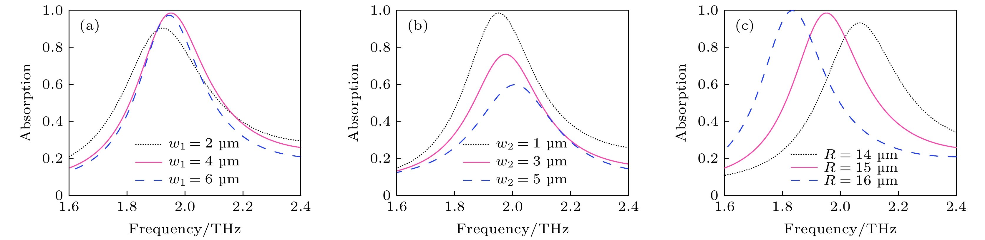
图 11 不同结构参数对线极化吸收影响 (a) w1; (b) w2; (c) R
Fig. 11. Influence of different structural parameters on linear polarization absorption: (a) w1; (b) w2; (c) R.
-
[1] Chen L, Liao D G, Guo X G, Zhao J Y, Zhu Y M, Zhuang S L 2019 Front Inform. Technol. Electron. Eng. 20 591
Google Scholar
[2] Xu B L, Zhong R B, Liang Z K, et al. 2022 Front Mater 9 881229
Google Scholar
[3] Zheng Z P, Luo Y, Yang H, et al. 2022 Phys. Chem. Chem. Phys. 24 8846
Google Scholar
[4] Zhang Y G, Qiu F, Liang L J, Yao H Y, Yan X, Liu W J, Huang C C, Yao J Q 2022 Opt. Express 30 24703
Google Scholar
[5] Tang B, Ren Y 2022 Phys. Chem. Chem. Phys. 24 8408
Google Scholar
[6] Luo H, Wang X, Qian H 2021 J. Opt. Soc. Am. B 38 2638
Google Scholar
[7] Aghili S, Amini A, Dizaj L S, Dolgaleva K 2022 Opt. Commun. 508 127805
Google Scholar
[8] Zhu L, Zhao X, Miao F J, Ghosh B K, Dong L, Tao B R, Meng F Y, Li W N 2019 Opt. Express 27 12163
Google Scholar
[9] Zhang Y D, Liu H Q, Xu R G, Qin Z J, Teng C X, Deng S J, Chen M, Cheng Y, Deng H C, Yang H Y, Qu S L, Yuan L B 2021 Opt. Express 29 21020
Google Scholar
[10] Wang X Y, Ma C, Xiao L H, et al. 2022 Appl. Opt. 61 1646
Google Scholar
[11] Li R, Pan M, Yi Z, Yu J X, Shi P C, Luo H, Wu P H, Yang H, Wang S F, Gao G C 2022 Opt. Laser Technol. 153 108284
Google Scholar
[12] Chen X Y, Tian Z, Lu Y C, Xu Y H, Zhang X Q, Ouyang C M, Gu J Q, Han J G, Zhang W L 2020 Adv. Optical Mater. 8 1900660
Google Scholar
[13] Hu N, Wu F L, Bian L A, Liu H Q, Liu P G 2018 Opt. Mater. Express 8 3899
Google Scholar
[14] 杨鹏 韩天成 2018 物理学报 67 107801
Google Scholar
Yang P, Han T C 2018 Acta Phys. Sin. 67 107801
Google Scholar
[15] Yan D X, Li J S 2019 Laser Phys. 29 046203
Google Scholar
[16] Divdel H, Taghipour-Farshi H, Saghai H R, Jahani M A T G 2020 Opt. Eng. 59 127108
Google Scholar
[17] Zhao Y, Zeng L, Zhang X L, Ye H N, Zhang H F 2021 J. Opt. 23 085102
Google Scholar
[18] Liang S, Zhu Z B, Jiang L Y 2022 Eng. Res. Express 4 035006
Google Scholar
[19] Li Z W, Li J S 2021 Appl. Opt. 60 2450
Google Scholar
[20] Mutlu M, Akosman A E, Serebryannikov A E, Ozbay E 2012 Phys. Rev. Lett. 108 213905
Google Scholar
[21] Wang T L, Zhang Y P, Zhang H Y, Cao M Y 2020 Opt. Mater. Express 10 369
Google Scholar

 下载:
下载:
计量
- 文章访问数: 7411
- PDF下载量: 136
- 被引次数: 0
