


Most Cited
2025, 74 (2): 027702.
doi: 10.7498/aps.74.20240906
Abstract +

2025, 74 (1): 012101.
doi: 10.7498/aps.74.20241201
Abstract +
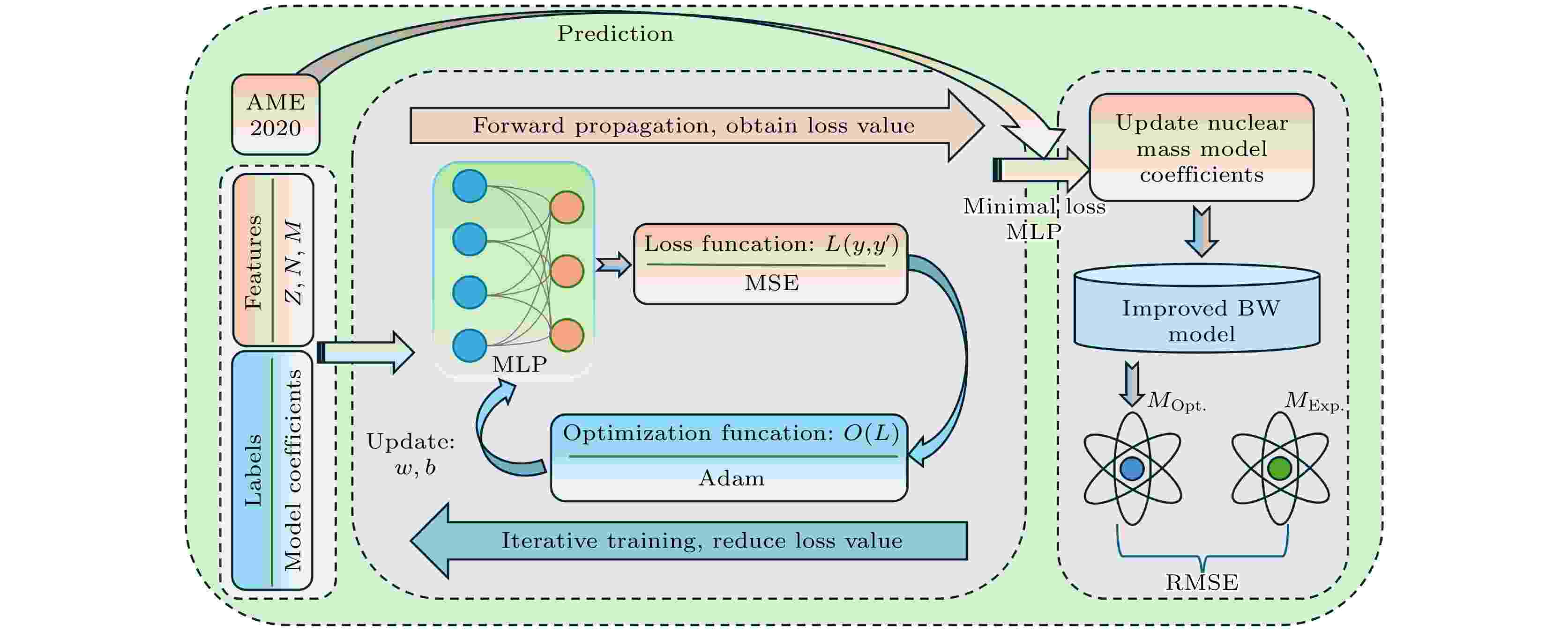
The nuclear mass model has significant applications in nuclear physics, astrophysics, and nuclear engineering. The accurate prediction of binding energy is crucial for studying nuclear structure, reactions, and decay. However, traditional mass models exhibit significant errors in double magic number region and heavy nuclear region. These models are difficult to effectively describe shell effect and parity effect in the nuclear structure, and also fail to capture the subtle differences observed in experimental results. This study demonstrates the powerful modeling capabilities of MLP neural networks, which optimize the parameters of the nuclear mass model, and reduce prediction errors in key regions and globally. In the neural network, neutron number, proton number, and binding energy are used as training feature values, and the mass-model coefficient is regarded as training label value. The training set is composed of the multiple sets of calculated nuclear mass model coefficients. Through extensive experiments, the optimal parameters are determined to ensure the convergence speed and stability of the model. The Adam optimizer is used to adjust the weight and bias of the network to reduce the mean squared error loss during training. Based on the AME2020 dataset, the trained neural network model with the minimum loss is used to predict the optimal coefficients of the nuclear mass model. The optimized BW2 model significantly reduces root-mean-square errors in double magic number and heavy nuclear regions. Specifically, the optimized model reduces the root-mean-square error by about 28%, 12%, and 18% near Z = 50 and N = 50; Z(N) = 50 and N = 82; Z = 82 and N = 126, respectively. In the heavy nuclear region, the error is reduced by 48%. The BW3 model combines higher-order symmetry energy terms, and after parameter optimization using the neural network, reduces the global root-mean-square error from 1.86 MeV to 1.63 MeV. This work reveals that the model with newly optimized coefficients not only exhibit significant error reduction near double magic numbers, but also shows the improvements in binding energy predictions for both neutron-rich and neutron-deficient nuclei. Furthermore, the model shows good improvements in describing parity effects, accurately capturing the differences related to parity in isotopic chains with different proton numbers. This study demonstrates the tremendous potential of MLP neural networks in optimizing the parameters of nuclear mass model and provides a novel method for optimizing parameters in more complex nuclear mass models. In addition, the proposed method is applicable to the nuclear mass models with implicit or nonlinear relationships, providing a new perspective for further developing the nuclear mass models.
2025, 74 (10): 108901.
doi: 10.7498/aps.74.20250179
Abstract +
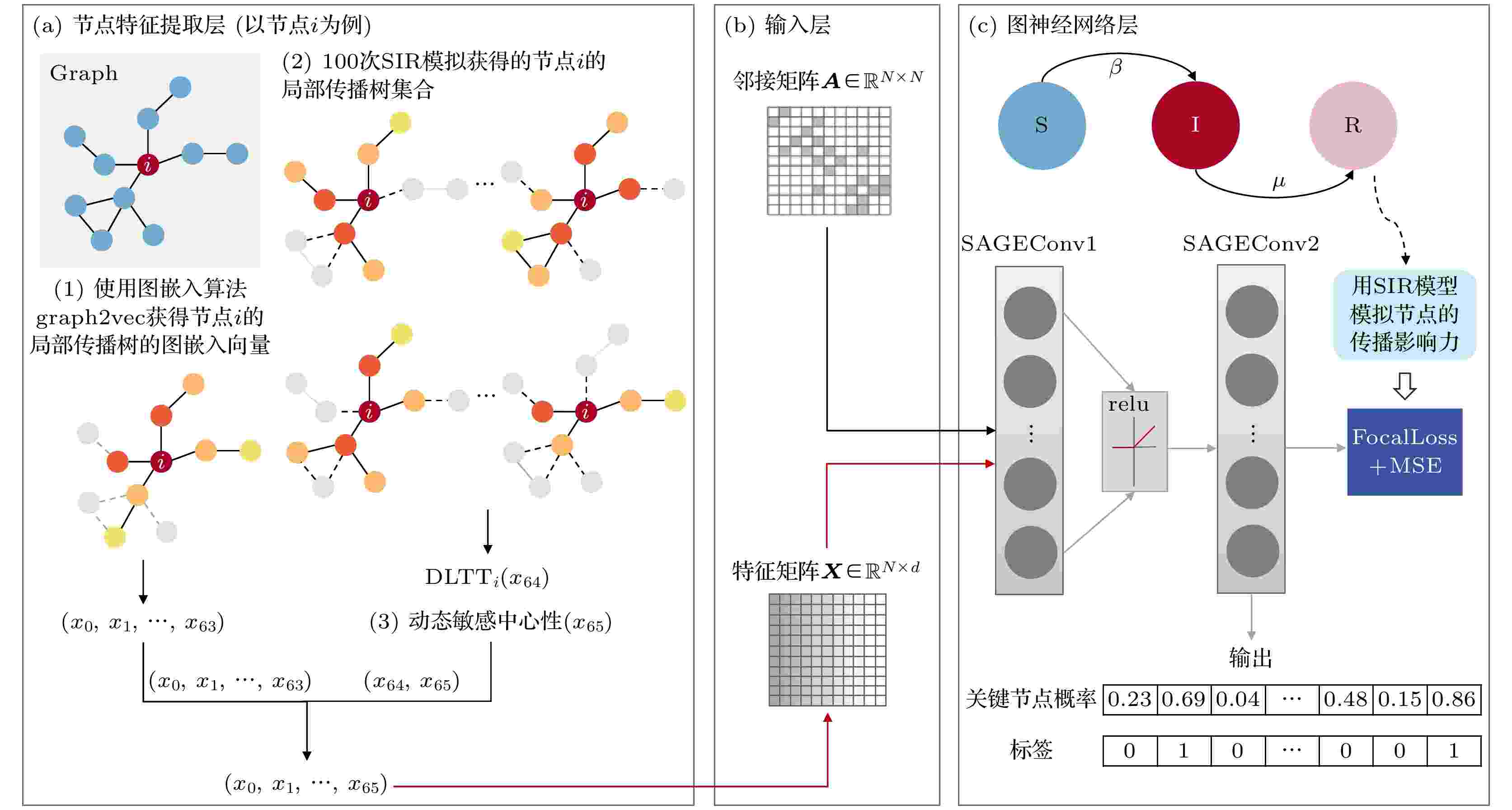
Identifying the most influential nodes in the spreading process in complex networks is crucial in many applications, such as accelerating the diffusion of information and suppressing the spread of viruses or rumors. Existing methods of identifying influential spreaders have their limitations. Specifically speaking, classical network centrality methods rely solely on local or global topology to predict node influence; traditional machine learning and deep learning methods are not suitable for graph-structured data; existing graph neural network-based methods neglect the dynamic characteristics of the propagation process itself. Researchers have pointed out that the spreading influence of nodes not only depends on their structural location, but is also significantly influenced by the dynamics of the spreading process itself. In this work, we propose a propagation dynamics graph neural network (PDGNN) that integrates the dynamic features of the propagation process and the structural features of nodes to identify influential nodes. Specifically speaking, based on the susceptible-infected-recovered (SIR) propagation model, the dynamic infection features and potential infection capacity of nodes are extracted from the epidemic spreading process. Then a high-dimensional feature vector of each node consisting of the embedding and degree of its local transmission tree, as well as its dynamics-sensitive centrality is constructed and used as the input to the graph neural network. To deal with the problem of imbalanced numbers between critical nodes and non-critical nodes in training the model and optimizing the output, an optimized loss function is designed, which combines focal loss with mean squared error. Experimental results in two synthetic networks and seven real-world networks show that the PDGNN outperforms classical centrality methods, traditional machine learning and deep learning-based methods, and existing graph neural network-based methods in identifying influential nodes in the spreading process in complex networks. The performance of PDGNN is robust when the infection rate and the size of the training set change. In a wide range of infection rates, the proposed PDGNN can accurately identify influential spreaders. Despite the fact that the training set accounts for 30% of the total dataset, the PDGNN has the smallest inaccuracy in all nine studied networks.
2025, 74 (1): 012801.
doi: 10.7498/aps.74.20241178
Abstract +
2025, 74 (2): 028102.
doi: 10.7498/aps.74.20241438
Abstract +
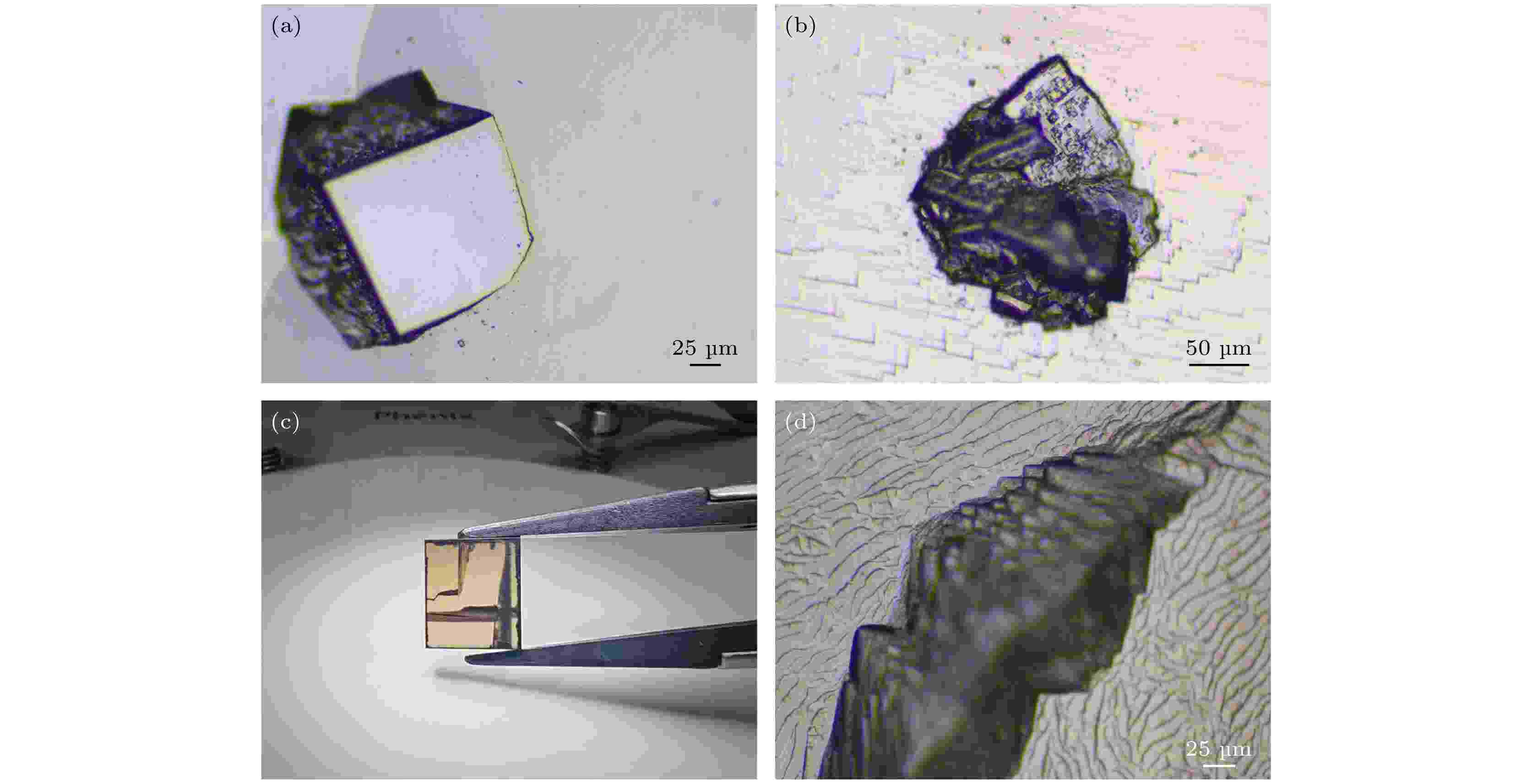
Diamond nitrogen vacancy (NV) color centers have good stability at room temperature and long electron spin coherence time, and can be manipulated by lasers and microwaves, thereby becoming the most promising structure in the field of quantum detection. Within a certain range, the higher the concentration of NV color centers, the higher the sensitivity of detecting physical quantities is. Therefore, it is necessary to dope sufficient nitrogen atoms into diamond single crystals to form high-concentration NV color centers. In this study, diamond single crystals with different nitrogen content are prepared by microwave plasma chemical vapor deposition (MPCVD) to construct high-concentration NV color centers. By doping different amounts of nitrogen atoms into the precursor gas, many problems encountered during long-time growth of diamond single crystals under high nitrogen conditions are solved. Diamond single crystals with nitrogen content of about 0.205, 5, 8, 11, 15, 36, and 54 ppm (1 ppm = 10–6) are prepared. As the nitrogen content increases, the width of the step flow on the surface of the diamond single crystal gradually widens, eventually the step flow gradually disappears and the surface becomes smooth. Under the experimental conditions in this study, it is preliminarily determined that the average ratio of the nitrogen content in the precursor gas to the nitrogen atom content introduced into the diamond single crystal lattice is about 11. Fourier transform infrared spectroscopy shows that as the nitrogen content inside the CVD diamond single crystal increases, the density of vacancy defects also increases. Therefore, the color of CVD high nitrogen diamond single crystals ranges from light brown to brownish black. Compared with HPHT diamond single crystal, the CVD high nitrogen diamond single crystal has a weak intensity of absorption peak at 1130 cm–1 and no absorption peak at 1280 cm–1. Three obvious nitrogen-related absorption peaks at 1371, 1353, and 1332 cm–1 of the CVD diamond single crystal are displayed. Nitrogen atoms mainly exist in the form of aggregated nitrogen and single substitutional N+ in diamond single crystals, rather than in the form of C-defect. The PL spectrum results show that defects such as vacancies inside the diamond single crystal with nitrogen content of 54 ppm are significantly increased after electron irradiation, leading to a remarkable increase in the concentration of NV color centers. The magnetic detection performance of the NV color center material after irradiation is verified, and the fluorescence intensity is uniformly distributed in the sample surface. The diamond single crystal with nitrogen content of 54 ppm has good microwave spin manipulation, and its longitudinal relaxation time is about 3.37 ms.
2025, 74 (1): 012501.
doi: 10.7498/aps.74.20241412
Abstract +
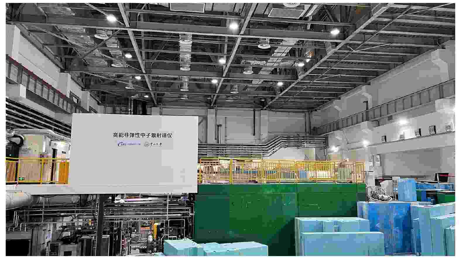
Inelastic neutron scattering is a pivotal technique in materials science and physics research, revealing the microscopic dynamic properties of materials by observing the changes in energy and momentum of neutrons interacting with matter. This technique provides important information for quantitatively describing the phonon dispersion and magnetic excitation of materials. Inelastic neutron scattering spectrometers can be divided into triple-axis spectrometers and time-of-flight spectrometers, according to the method of selecting monochromatic neutrons. The former has high signal-to-noise ratio, flexibility, and precise tracking capabilities for specific measurement points, while the latter significantly improves experimental efficiency through various measures. The application of inelastic neutron scattering spectrometers is quite extensive, playing an indispensable role in advancing frontier scientific research in the study of mechanisms in various materials such as magnetism, superconductivity, thermoelectrics, and catalysis. The high-energy inelastic spectrometer at the China Spallation Neutron Source is the first time-of-flight neutron inelastic spectrometer in China, achieving high resolution and multi-energy coexistence with its innovative Fermi chopper design. Additionally, the number of available single neutron beams in the experiment of this facility has reached the international leading level.
2025, 74 (1): 017401.
doi: 10.7498/aps.74.20241534
Abstract +
2025, 74 (3): 038801.
doi: 10.7498/aps.74.20240941
Abstract +
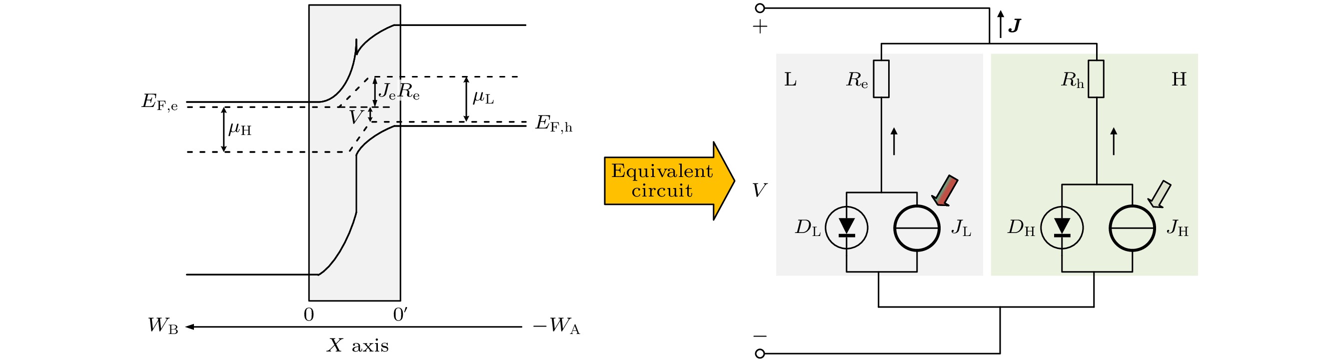
The ideal solar cell defined by the Shockley-Queisser (S-Q) theory is an important milestone in the analysis of photovoltaic devices based on some assumptions. One or more of the above assumptions are gradually avoided, and even exceed or approach the S-Q efficiency limit, so the development and improvement of S-Q theory is necessary. Heterojunction solar cells are one of the hot research fields in photovoltaics. In order to address the hindering effect of energy band discontinuity in the spatial barrier region of heterojunction solar cells on the transport of photogenerated carriers, the assumptions of S-Q theory based on the original S-Q theory of photovoltaic cells are revised in this work. The carrier mobility in the barrier region is assumed to be finite, and the infinite mobility in the S-Q model is abandoned. But the mobility in the N-type and the P-type neutral region are still infinite. The lumped relationship between carrier mobility and resistance in the barrier region is derived. Therefore, the physical process of charge transport is described in detail in this paper based on the continuity equation for semiconductors by considering the effect of absorption coefficients to prevent the quasi-Fermi level from crossing the conduction or valence band. Thus, the revised S-Q theoretical limit model of heterojunction solar cell is constructed. The diode equivalent circuit diagram is deduced and the photovoltaic conversion efficiency is evaluated eventually. The loss effects of charge transmission and band gap mismatch on the performance of heterojunction solar cells are analyzed in detail. The calculation results under the condition of 5780 K blackbody radiation and 300 K cell temperature with N-type wide bandgap (EH) and P-type narrow bandgap (EL) materials show that the highest conversion efficiency is about 31% with a hole resistance of 0.01 Ω·cm2 and electronic resistance of 0.01 Ω·cm2. The calculations show that the electronic resistance has a more negative and complicated effect on solar cell performance than hole resistance. When Re and Rh are small, the best conversion efficiency is in a range between 1.22 eV and 1.32 eV of the narrow bandgap. Increasing Re can increase the open circuit voltage of solar cells, but there are losses in efficiency and fill factor of solar cells. When Re is large enough, for example, Re = 1000 Ω·cm2, the open circuit voltage of solar cells is not limited by EL and can exceed the bandgap limit of the narrow bandgap material. Increasing Rh will also reduce efficiency, but the effect is not so great as Re. The change of absorption coefficient can cause the photogenerated current of L and H branches to change, and the radiation recombination losses of both branches can be regulated.
2025, 74 (1): 017501.
doi: 10.7498/aps.74.20240662
Abstract +
Selective laser melting (SLM) has potential to prepare complex shaped amorphous alloy parts, however, the almost inevitable crystallization makes it very difficult to obtain excellent performance parts. Most of previous studies focus on improving properties by optimizing parameters such as laser power, scanning speed, and scanning strategy. As is well known, the substrate is an important component in SLM devices, which directly supports and contacts the initial powder and melting pool, affecting the absorption and transfer of heat, the formation and cooling of the melting pool, and therefore exerts a significant influence on the quality and microstructure of printed parts. However, there is relatively little research on its influence. It is important and necessary to understand the influence of substrate temperature on crystallization behavior of Fe-based amorphous alloy during SLM process. Molecular dynamics (MD) simulations can provide direct evidence for the evolution of clusters and band pairs, which can help clarify the crystallization mechanism and alleviate the crystallization. In this work, the influence of substrate temperature on the crystallization and evolution of atomic clusters in Fe50Cu25Ni25 amorphous alloy during SLM is investigated on an atomic scale, using MD simulation under different substrate temperatures (300–900 K), laser power values (500–800 eV/ps), and scanning speeds (0.1–1.0 nm/ps). The research results show that when the substrate temperature is lower than 750 K, the content of characteristic bond pair 1421 and the corresponding $ \left\langle{0,{\mathrm{ }}4,{\mathrm{ }}4,{\mathrm{ }}6}\right\rangle $ cluster increase with the substrate temperature rising, thereby increasing face-centered cubic bond pair and cluster and promoting the crystallization. When the substrate temperature rises to a value close to the glass transition temperature, the evolution of bond pairs and clusters becomes complex, which is influenced by the collaborative and competitive effects, such as the ability to form glass, melting and cooling rate. This work reveals the evolution of atomic clusters and band pairs in the SLM process of Fe-based amorphous alloys, and the initiation of crystal phases at different substrate temperatures, providing new ideas for understanding and regulating crystallization.
2025, 74 (9): 090304.
doi: 10.7498/aps.74.20241262
Abstract +
This paper reviews the physical principles, development history of related application research, current research status and prospects of the Josephson voltage standard (JVS) working at liquid helium temperatures. The JVS working at liquid helium temperature has advantages of high mobility and low-energy consumption, and has a broad application prospect. This paper describes the research status of Josephson voltage standards, focusing on the possibility of developing a JVS based on high-temperature superconductors, and the challenges in chip preparation. In addition, a newly developed preparation technology for Josephson junction, namely the focused helium ion beam, is introduced. It has advantages in the preparation of high consistent Josephson junction arrays in high consistency. Therefore, it is a possible technical route for exploring the realization of JVS working at liquid helium temperature in the future.
2025, 74 (2): 024203.
doi: 10.7498/aps.74.20241352
Abstract +
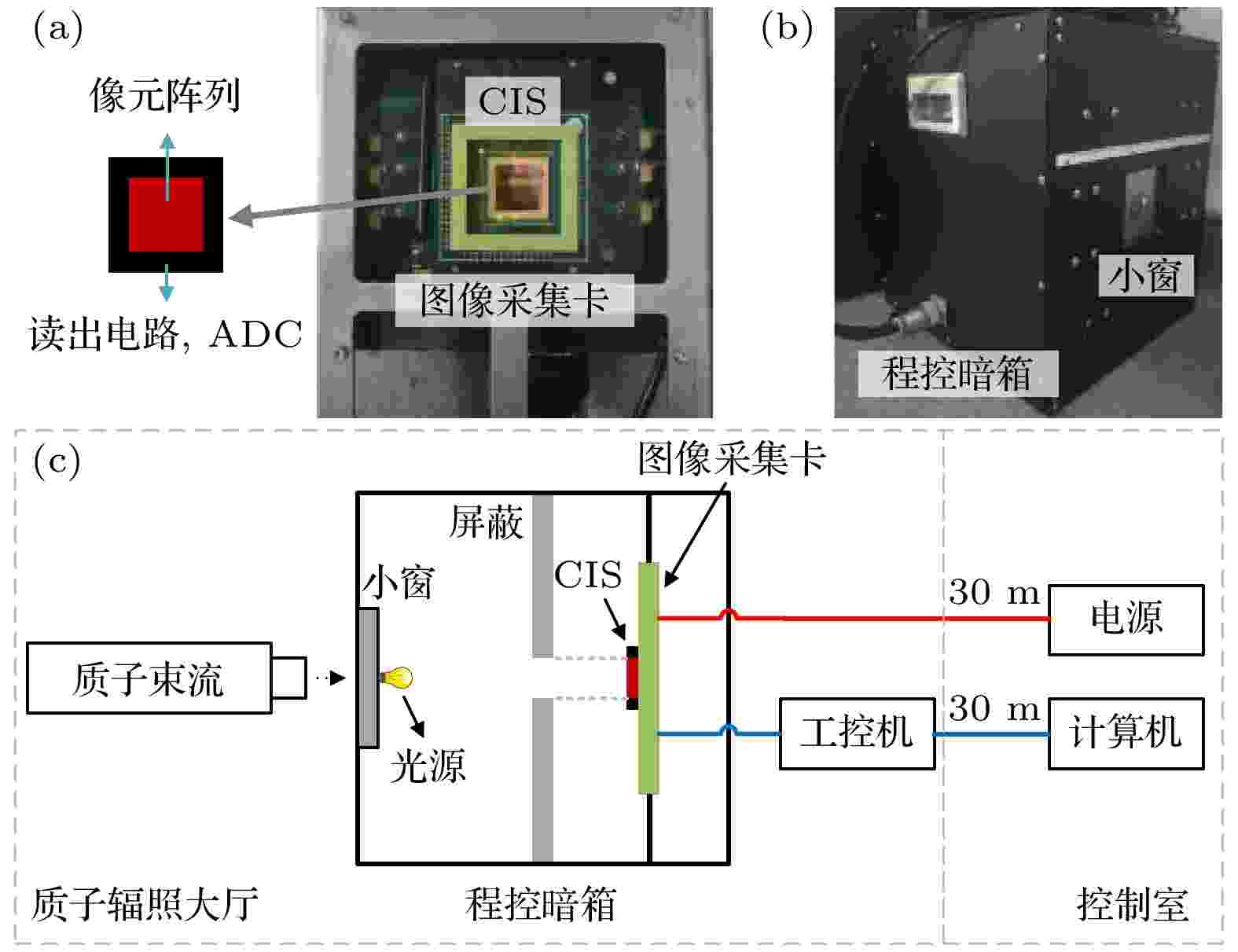
Complementary metal oxide semiconductor (CMOS) image sensors have been increasingly widely used in the field of radiation environments due to their numerous advantages, and their radiation effects have also attracted much attention. Some experimental studies have shown that the saturation output of CMOS image sensors decreases after irradiation, while others have reported that it increases. In this work, the further in-depth research on the inconsistent results is conducted based on the proton irradiation experiments and TCAD simulations, and the degradation mechanism in full well capacity, conversion factor, and saturation output of the 4T pinned photodiode (PPD) CMOS image sensors due to proton cumulative radiation effects are also analyzed. In experiments, the sensors are irradiated by 12 MeV and 60 MeV protons with a fluence up to 2× 1012 cm–2. The sensors are unbiased during irradiation. The experimental results show that proton irradiation at 12 MeV and 60 MeV result in an increase of 8.2% and 7.3% in conversion factor, respectively, and a decrease of 7.3% and 3.8% in full well capacity, respectively. The saturation output shows no significant change trend under 12 MeV proton irradiation, but increases by 3% under 60 MeV proton irradiation. In the TCAD simulation, a three-dimensional 4T PPD pixel model is constructed. A simulation method that combines the trap and gamma radiation model in TCAD with the mathematical model of minority carrier lifetime is used to simulate global and local cumulative proton irradiation in order to analyze the degradation mechanism. It is proposed that the degradation of saturation output at the pixel level is determined by the full well capacity of PPD, the physical characteristics of the reset transistor and the capacitance of floating diffusion, but they have opposite effects. Proton irradiation leads to the accumulation of oxide-trapped positive charges in the shallow trench isolation on both sides of PPD, resulting in the formation of leakage current path in silicon, thereby reducing the full well capacity. A decrease in full well capacity leads to a decrease in saturation output. While, the radiation effect of the reset transistor causes the potential of floating diffusion (FD) to increase during the FD reset phase, further leading to an increase in saturation output. The irradiation causes the capacitance of the floating diffusion to decrease, resulting in an increase in conversion factor and consequently increasing the saturation output. The difference in radiation sensitivity among the three influence factors at the pixel level may result in a decrease or increase in saturation output with proton fluence increasing. The above work comprehensively reveals and analyzes the mechanisms of degradation in full well capacity, conversion factor and saturation output after irradiation, and the research results have certain guiding significance for analyzing the radiation damage to CMOS image sensors.
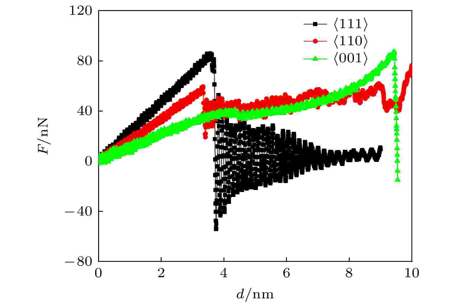
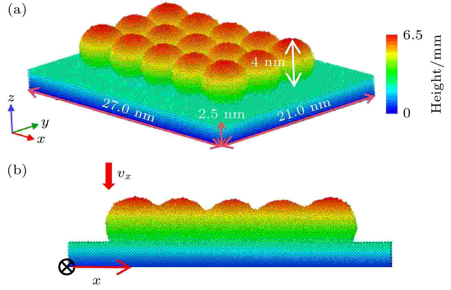
2025, 74 (3): 036201.
doi: 10.7498/aps.74.20241030
Abstract +
In nanosystems, the metallic nanowires are subjected to significant and cyclic bending deformation upon being integrated into stretchable and flexible nanoelectronic devices. The reliability and service life of these nanodevices depend fundamentally on the bending mechanical properties of the metallic nanowires that serve as the critical components. An in-depth understanding of the deformation behavior of the metallic nanowires under bending is not only essential but also imperative for designing and manufacturing high-performance nanodevices. To explore the mechanism of the bending plasticity of the metallic nanowire, the bending deformations of B2-FeAl alloy nanowires with various crystallographic orientations, sizes and cross-sectional shapes are investigated by using molecular dynamics simulation. The results show that the bending behavior of the B2-FeAl alloy nanowires is dependent on neither their size nor cross-sectional shape of the nanowire, but it is highly sensitive to its axial orientation. Specifically, both $\left\langle {111} \right\rangle $- and $\left\langle {110} \right\rangle $-oriented nanowires are generated through dislocation nucleation during bending, with the $\left\langle {111} \right\rangle $-oriented nanowires failling shortly after yielding due to brittle fracture, while the $\left\langle {110} \right\rangle $-oriented nanowires exhibit good ductility due to uniform plastic flow caused by continuous nucleation and stable motion of dislocations. Unlike the aforementioned two nanowires, the bending plasticity of the $\left\langle {001} \right\rangle $-oriented nanowire is mediated by the stress-induced transition from B2 phase to L10 phase, which leads to excellent ductility and higher fracture strain. The orientation dependence of bending deformation can be understood by considering the Schmid factor. Moreover, the plastically bent nanowires with $\left\langle {110} \right\rangle $ and $\left\langle {001} \right\rangle $ orientation are able to recover to their original shape upon unloading, particularly, the plastic deformation in the $\left\langle {001} \right\rangle $-oriented nanowire is recoverable completely via reverse transformation from L10 to B2 structures, exhibiting superelasticity. This work elucidates the deformation mechanism of the B2-FeAl alloy nanowires subjected to bending loads, which provides a crucial insight for designing and optimizing flexible and stretchable nanodevices based on metallic nanowires.
2025, 74 (2): 025201.
doi: 10.7498/aps.74.20241330
Abstract +
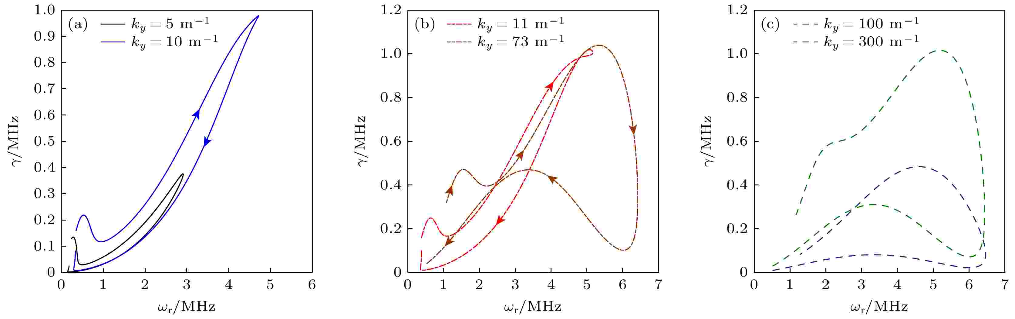
The free energy contained in electron drift, electron collision, and plasma density gradient, temperature, magnetic field gradient can trigger off the instabilities with different frequencies and wavelengths in hall thrusters. The instabilities will destroy the stable discharge of plasma, affecting the matching degree between the thruster and the power processing unit, and reducing the performance of the thruster. Based on this, the instabilities triggered off by electron collision, plasma density gradient, and magnetic field gradient in the hall thruster are studied by using dispersion relation derived from the fluid model. The results are shown below. 1) When in the model includes the effects of electron inertia, collision between electrons and neutral atoms, and electron drift, instability can be excited at any axial position from the near anode region to the plume region of the thruster. With the increase of azimuthal wavenumber ${k_y} = 2\pi /\lambda $, the lower-hybrid mode excited by electron collision transitions into the ion sound mode, where ${k_y} = 2{\text{π }}/\lambda $, $\lambda $being the wave length. The real frequency ${\omega _{\text{r}}}$ corresponding to the maximum growth rate ${\gamma _{\max }}$ slightly decreases with collision frequency increasing for ${k_y} = 10{\text{ }}{{\text{ m}}^{ - 1}}$. However, the maximum real frequency and real frequency ${\omega _{\text{r}}}$ corresponding to the maximum growth rate ${k_y} = 300{{\text{ m}}^{ - 1}}$ will not change with collision frequency for ${k_y} = 300{\text{ }}{{\text{ m}}^{ - 1}}$. Independent of the value of ${k_y}$, the growth rate of mode triggered off by electron collision increases with collision frequency increasing. 2) The plasma density gradient effect plays a dominant role in triggering off instabilities when the electron inertia, electron-neutral collisions and plasma density gradient are simultaneously included in the model. The dynamic behavior of the model does not change with the increase of ${k_y}$, but the eigenvalue of the model increases with the ${k_y}$ increasing. Since the sign of anti-drift frequency induced by the plasma density gradient is changed, the mode eigenvalues have the opposite change trend on both sides of point ${\kappa _{\text{N}}}$. When the sign of ${\omega _r}$ and ${\omega _r}$ are opposite, the density gradient effect has a stabilization effect on instability excitation (${\kappa _{\text{N}}} > 0$). When the sign of ${\omega _{\text{s}}}$ and ${\omega _{\text{r}}}$ are the same, the density gradient effect enhances the excitation of instability (${\kappa _{\text{N}}} < 0$). 3) If the plasma density gradient, magnetic field gradient, electron inertia and electron-neutral collisions are included in the dispersion, the mode eigenvalue relies on the electron drift frequency, and the diamagnetic drift frequency induced by the density gradient and magnetic field gradient. When the density gradient effect and the magnetic field gradient effect are considered, there is a stable window in the discharge channel. However, if the electron inertia and electron-neutral collisions are also included, the stable window will disappear.
Finite element prediction and device performance of piezoelectric fiber composite based smart sensor
2025, 74 (5): 057701.
doi: 10.7498/aps.74.20241379
Abstract +
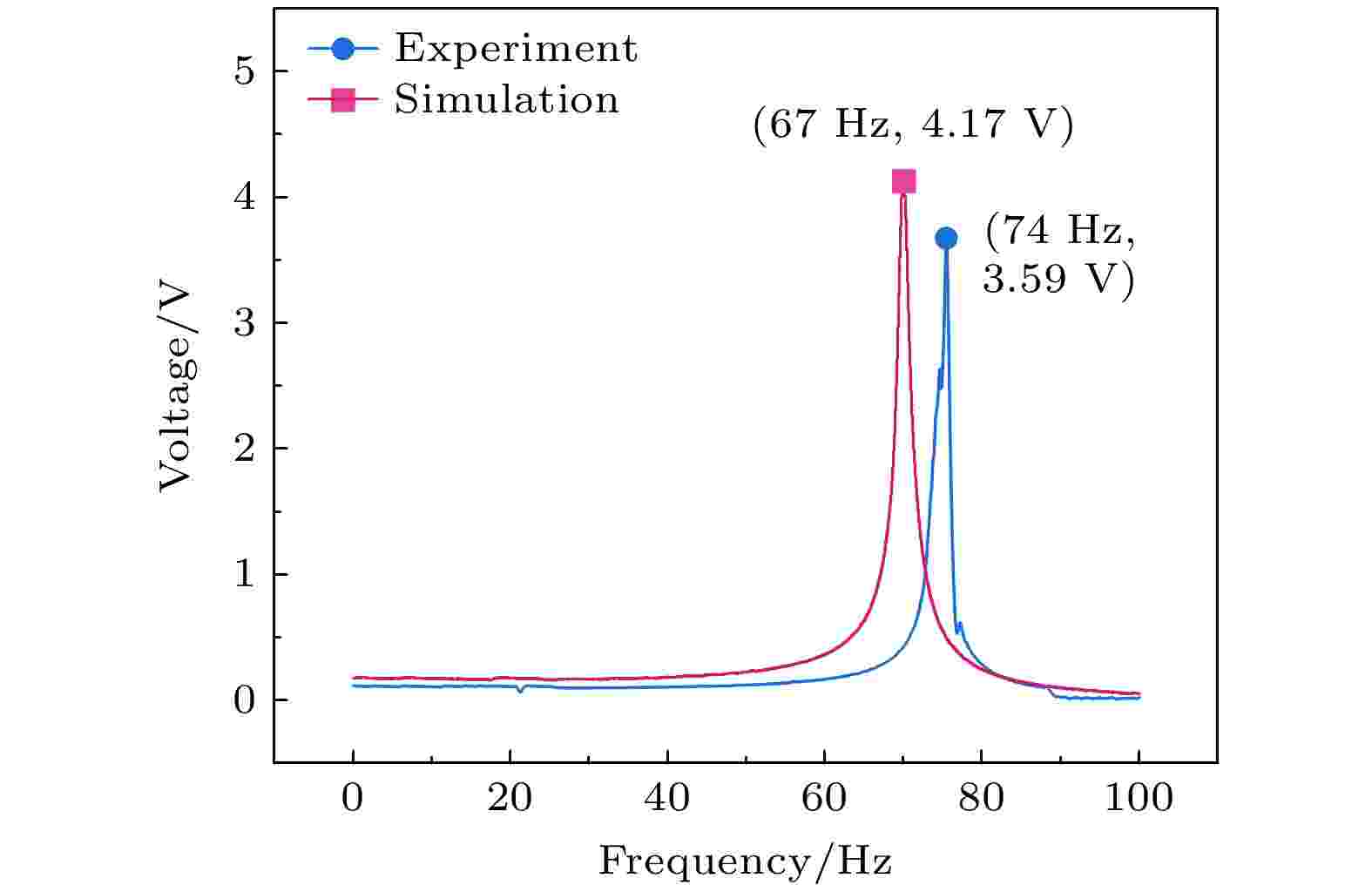
Macro fiber composite (MFC) is extensively utilized in aviation, aerospace, civilian, and military domains due to its high piezoelectricity, flexibility, and minimal loss. Nevertheless, existing research on MFC sensors has focused on material applications, with a conspicuous lack of systematic investigation into the simulation and modeling of MFC sensor devices. In this study, three models, namely, a representative volume element (RVE) model, a direct model, and a Hybrid model are established to analyze the finite element models of MFC, covering the scales from micro to macro. On the one hand, the equivalent RVE model contributes to an understanding of the internal electric field distribution in MFC, thereby establishing a theoretical foundation for force-electric coupling. On the other hand, the application of the direct model and hybrid model accords with the boundary conditions in MFC applications, which lays a theoretical foundation for the stress sensing and resonance sensing mechanisms of MFC. These models constitute effective tools for predicting the sensing performance of MFC smart element sensors. The simulation outcomes indicate that resonant sensors exhibit significantly superior performance compared with patch sensors. Under the conditions where the excitation acceleration is 5 m/s² and the cantilever substrate length is 80 mm, the simulated resonant frequency of the MFC resonant sensor is 67 Hz, with an output voltage of 4.17 V. Experimental results confirm these findings. It is reported that the resonant frequency is 74 Hz and the output voltage is 3.59 V for the MFC sensor. The remarkable consistency between the simulation results and experimental data of the MFC sensor deserves to be emphasized. In addition, the MFC sensor shows excellent sensing sensitivity at low frequencies, with a sensitivity of 7.35 V/g. Obviously, MFC shows remarkable sensing characteristics at low-frequency resonance. The three finite element models established in this work can well predict the sensing performance of MFC sensors, thus ensuring reliable prediction of the performance of such sensors.
2025, 74 (1): 014203.
doi: 10.7498/aps.74.20241458
Abstract +
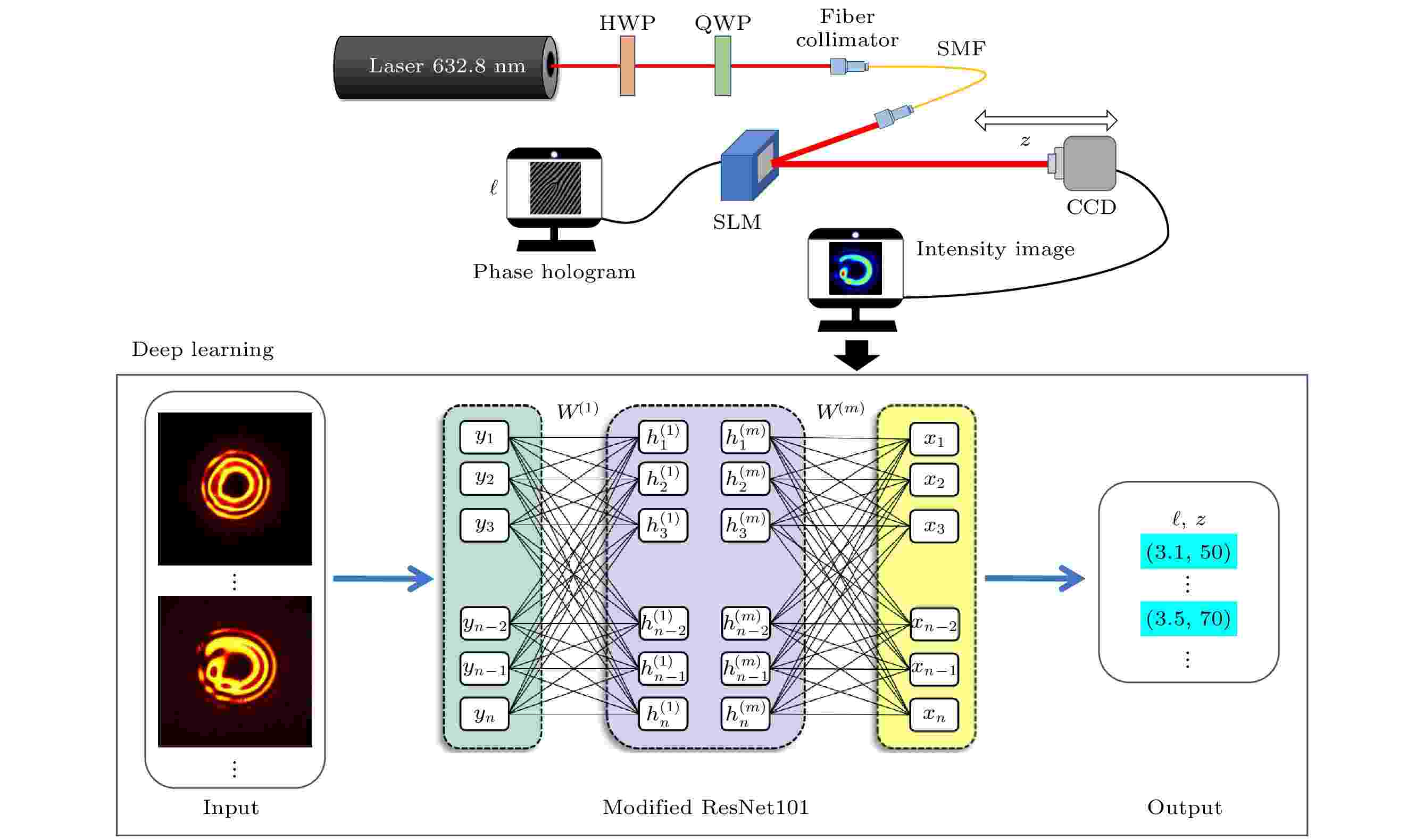
Fractional-order vortex beams possess fractional orbital angular momentum (FOAM) modes, which theoretically have the potential to increase transmission capacity infinitely. Therefore, they have significant application prospects in the fields of measurement, optical communication and microparticle manipulation. However, when fractional-order vortex beams propagate in free space, the discontinuity of the helical phase makes them susceptible to diffraction in practical applications, thereby affecting the accuracy of OAM mode recognition and severely limiting the use of FOAM-based optical communication. Achieving machine learning recognition of fractional-order vortex beams under diffraction conditions is currently an urgent and unreported issue. Based on ResNetA, a deep learning (DL) method of accurately recognizing the propagation distance and topological charge of fractional-order vortex beam diffraction process is proposed in this work. Utilizing both experimentally measured and numerically simulated intensity distributions, a dataset of vortex beam diffraction intensity patterns in atmospheric turbulence environments is created. An improved 101-layer ResNet structure based on transfer learning is employed to achieve accurate and efficient recognition of the FOAM model at different propagation distances. Experimental results show that the proposed method can accurately recognize FOAM modes with a propagation distance of 100 cm, a spacing of 5 cm, and a mode spacing of 0.1 under turbulent conditions, with an accuracy of 99.69%. This method considers the effect of atmospheric turbulence during spatial transmission, allowing the recognition scheme to achieve high accuracy even in special environments. It has the ability to distinguish ultra-fine FOAM modes and propagation distances, which cannot be achieved by traditional methods. This technology can be applied to multidimensional encoding and sensing measurements based on FOAM beam.
2025, 74 (1): 014202.
doi: 10.7498/aps.74.20241126
Abstract +
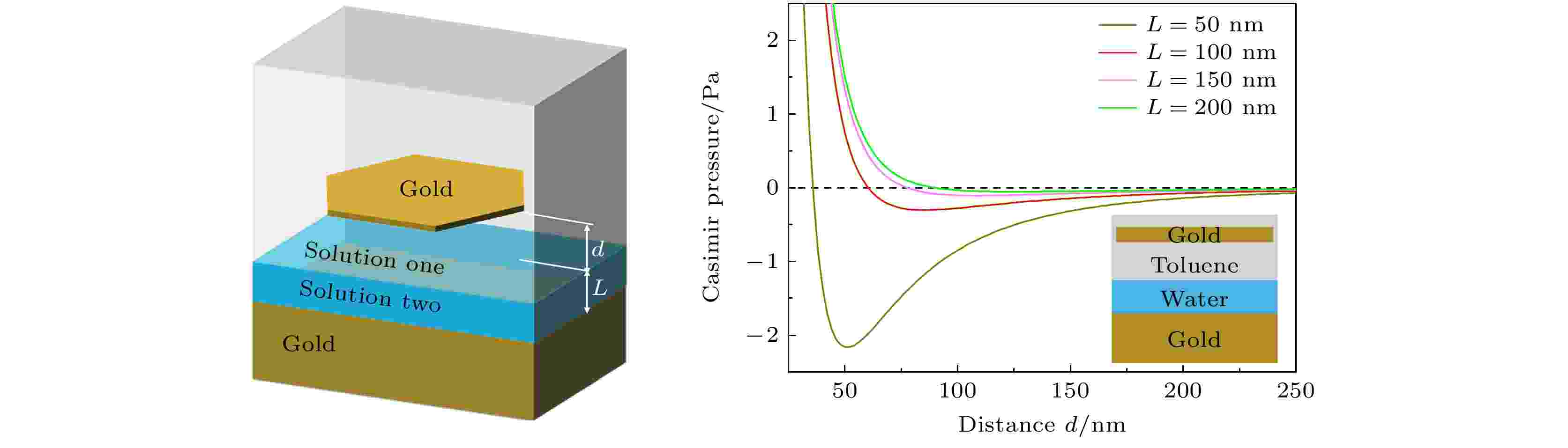
The Casimir effect, a macroscopic manifestation of quantum phenomena, arises from zero-point energy and thermal fluctuations. When two objects are brought into close proximity, the Casimir effect manifests as a repulsive force, while at greater separations, it transforms into an attractive force. There exists a specific distance at which the Casimir force vanishes, which is referred to as the stable Casimir equilibrium. Stable Casimir equilibrium arises from the curve minimum value of the Casimir energy, which can create spatial trapping. The manipulation of stable Casimir equilibrium provides promising applications in fields such as tunable optical resonators and self-assembly. This work presents a scheme for achieving tunable Casimir equilibrium in a dual-liquid system. The system comprises a multilayered stratified structure with a gold substrate. Above the gold substrate, a stratified liquid system is formed due to the immiscibility between organic solutions and water. The lower-density solution is at the top, while the higher-density solution is at the bottom. Our results suggest that a stable Casimir equilibrium for a suspended gold nanoplate can be realized, when the suspended gold nanoplate is immersed in organic solution of toluene or benzene. Moreover, the height of the suspended gold nanoplate, determined by the stable Casimir equilibrium, can be precisely tuned by changing the thickness of the water layer. The effects of finite temperature and ionic concentration on the Casimir equilibria are also analyzed in this work. The results suggest that the separation height of Casimir equilibrium decreases with the increase of temperature. Interestingly, when the Debye shielding length is comparable to or smaller than the separation length, the ion concentration in water significantly affects the Casimir pressure allowing for extensive modulations of Casimir equilibrium. This work opens up a new avenue for adjusting Casimir equilibrium and has important applications in “quantum trapping” of micro-nano particles.
2025, 74 (1): 014501.
doi: 10.7498/aps.74.20241206
Abstract +
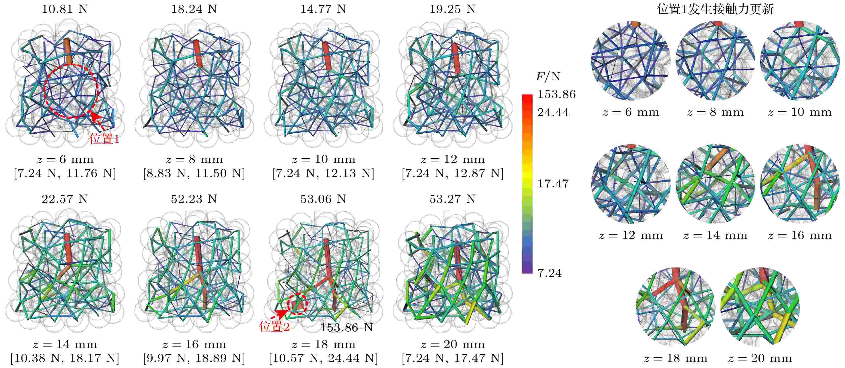
The calculation of inter-granule contact force in three-dimensional (3D) granular systems is a key and challenging aspect of granular mechanics research. Two elastic rubber balls are used as research objects for in-situ flat pressing micro-CT experiments. Based on the Hertzian contact theory and Tatara large deformation contact theory, the contact model of elastic balls is verified, and the theoretical formula of the contact force of elastic balls based on the experiment is obtained. Taking the 3D granular systems as research object, in-situ probe loading experiment of micro-CT is carried out to obtain the 2D image sequence of the granules, after a series of digital transformations, the digital body images emerge, the contact force networks of the 3D granular systems under different loading conditions are obtained by constructing pore network models. The contact force distribution and evolution law of the granular systems are analyzed. The relation among the number of strong contacts, the distribution evolution, and the stability of the granular system is explored. The results show that the two elastic ball contact model conforms to the Hertzian contact theory and Tatara large deformation contact theory, and the contact force fitting formula based on experiment can characterize the contact force between two granules reasonably and effectively. The contact force of granules under probe loading is distributed in a net-like pattern starting from the contact point of the indenter and gradually transmitted to the lower and the surrounding area. The trend of average contact force is consistent with the trend of the contact times, showing a significant phase transition. With the increase of contact times, the frequency of particle compression increases, resulting in a greater contact force between granules, ultimately stabilizing at about 10.5 N. The number of strong contacts accounts for 45% to 50% of the total number of contacts, distributed throughout the whole granular system and supporting the network structure of the granular system. The larger values are concentrated below the indenter and exhibit a branching distribution. In the loading process, an equilibrium point is established at z = 14 mm, where the number of strong contacts reaches the peak. The network structure of strong contact force is spread throughout the entire 3D granular system, establishing the main skeleton that can withstand external loads. As the loading continues, the total value of strong contact forces increases, and their distribution within the granular system becomes more uniform.
2025, 74 (2): 025202.
doi: 10.7498/aps.74.20241241
Abstract +
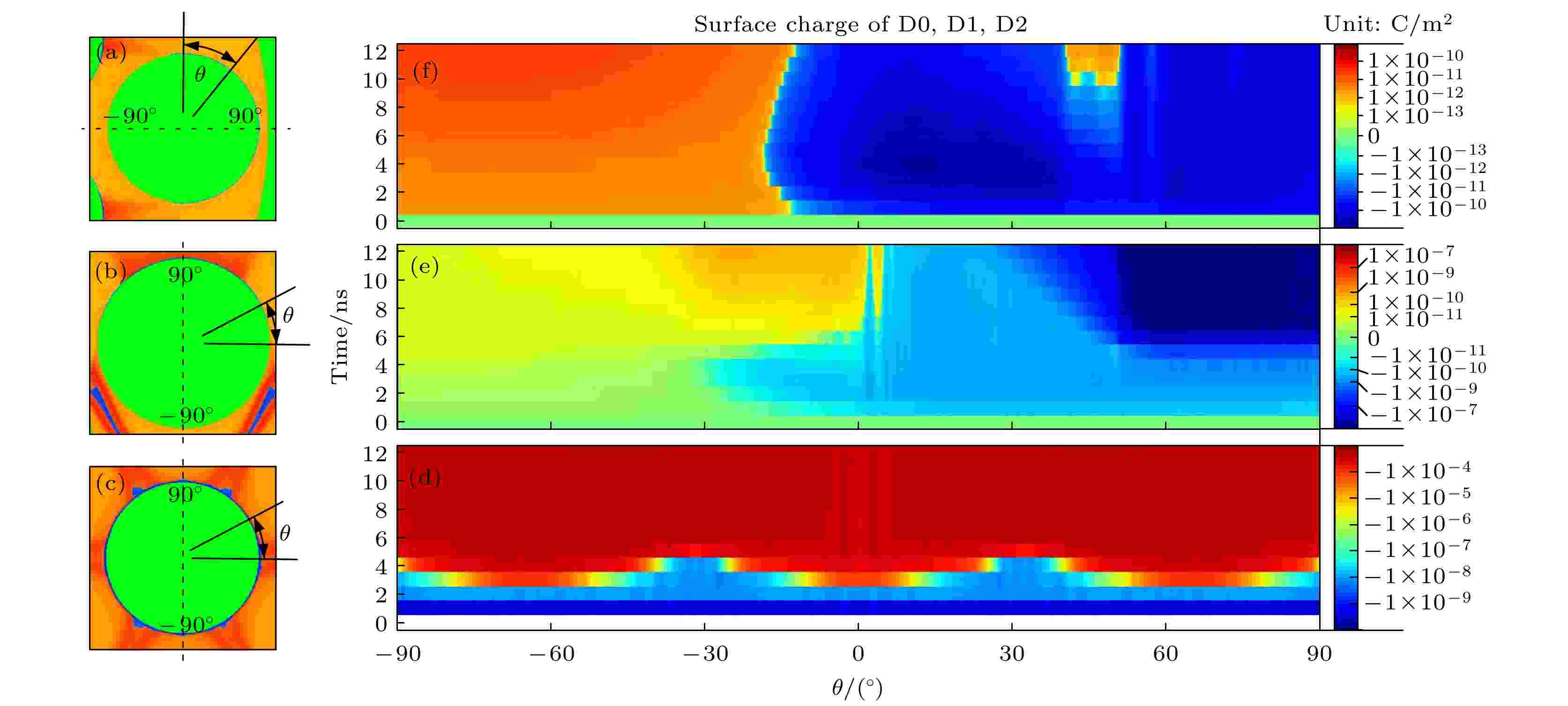
The streamer propagation and electric field distribution in a two-dimensional fluid model of a packed bed reactor (PBR) filled with carbon dioxide are comprehensively studied by utilizing the PASSKEy simulation platform in this work. The spatiotemporal evolution of electron density, electric fields and key plasma species in the discharge process are studied in depth. The PBR with layered dielectric spheres is simulated by using the model, indicating that the inner sides of the first layer and the second layer of dielectric spheres are not the main regions for reactions such as CO2 dissociation; instead, the main regions are along the streamer propagation path and the outer side of the first layer of dielectric sphere. In this work, the propagation of streamers in an electric field is investigated, highlighting the influence of anode voltage rise and dielectric polarization on local electric field enhancement. This enhancement leads the electron density and temperature to increase, which facilitats streamer propagation and the formation of filamentary microdischarges and surface ionization waves. This work provides a detailed analysis of the local electric field evolution at specific points within the PBR, and a further investigation of the spatiotemporal dynamics of spatial and surface charges, revealing that negative charges concentrate in the streamer and on the dielectric surface, with density being significantly higher than that of positive charges. The positive charge distribution is closely related to the streamer path, and with time going by, the charge distribution becomes dominated in the discharge space. This work also explores the surface charge deposition on the dielectric spheres, and discusses the evolution trend of the distribution. Additionally, this work discusses the temporal and spatial evolution of key plasma species, including ions and radicals, and their contributions to the overall discharge characteristics. The production mechanisms of carbon monoxide particles, carbon dioxide ions, and oxygen ions are analyzed, with a focus on their spatial distribution and correlation with electron density. Finally, the energy deposition within the PBR is examined by integrating the spatial energy deposition of electrons and major positive ions. The results indicate a total energy deposition value of approximately 1.428 mJ/m, with carbon dioxide ions accounting for 8.8% of this value.
2025, 74 (1): 010301.
doi: 10.7498/aps.74.20240933
Abstract +

- 1
- 2


